PEX Pipe in Residential Subfloor Thermal Mass

AI Thread Summary
A Thermal Mass system is being installed in a residential home using PEX pipes embedded in concrete for heating and cooling. The project aims to optimize heat transfer by determining the appropriate size and length of PEX tubing, with considerations for water velocity and pump power efficiency. Insulation strategies are discussed, emphasizing the importance of minimizing heat loss through proper insulation under and around the foundation. The conversation also addresses the choice of PEX over metal piping, highlighting the effectiveness of PEX in transferring heat when spaced correctly. Overall, the focus is on maximizing thermal efficiency while balancing system design and energy consumption.
DoctorLem
Messages
2
Reaction score
0
TL;DR Summary
I am installing a Thermal Mass in the center of our home. We are looking to figure out how much PEX pipe and what diameter for proper thermal transfer.
Hello friends!

We are installing a future provision for a Rocket Mass-type woodstove in our home.

This is a future project but realized that we could take advantage of the open area between the footing and finished floor by adding an insulated block of concrete with PEX pipes for Heating and Cooling Thermal Mass. The intention being to charge the Mass with heat from outside boiler, plate collectors, evac tube collectors, ext. Assuming water temp would be around 100ºF entering Mass. Summertime use would be for cooling with a buried loop system.

The Mass material will either be concrete or rammed earth, isolated from the stem walls and footing with 2" rigid foam, capped with stained concrete at finished floor level.

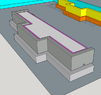
The volume measures around 22" high, throughout, 20ish' wide and between 3-6' deep, depending on where you measure in the "T" shaped foundation. This will be around 2.7 cubic yards of mass plus the top slab (the eventual fireplace will rest on the top slab).

The main questions being:

-What size PEX would be preferable?
-What amount of linear feet would I use to get maximum thermal transfer?
-What water velocity would I need to plan on achieving for water flow?

Thanks for any assistance in finding resources!
 
Engineering news on Phys.org
DoctorLem said:
Thanks for any assistance in finding resources!
It might be too late, but a better approach is to insulate under and outside the footings and basement walls. My own house has 4" foam insulation under the footings and outside the crawlspace walls.

Resources:
Search hydronic heating system design to find a number of good hits. Amazon also has a number of books that look good - search hydronic heating.

Short version is that you select the total length of tubing based on the amount of heat transferred in BTU per hour, then select the tubing size and configuration to match the circulating pump. The configuration is the mix of series and parallel in the tubing layout. You will need to study resources from the above searches to learn about pipe pressure loss (AKA head loss), and pump curves. It's good practice to design for minimum pump power. Good search term is pressure loss in pipe. Lots of good hits with those words.

A very rough guess is that you will need at least 100 feet of tubing in the concrete, and possibly as much as 500 feet. More tubing gives more heat transfer and requires more pump power, unless you make some parallel loops. There is an optimum tubing length, but it's a broad optimum, so you do not need extremely detailed calculations.

Any water velocity will transfer heat. Higher velocity has a higher heat transfer coefficient, but requires more pump power. Lower velocity will require more tubing, while allowing a smaller pump. Pump power adds up. It can be a surprisingly large portion of your electric bill. My personal preference would be for more tubing and a smaller pump to save energy.
 
These are all great considerations! As much material as it will take to complete this, I'm hoping that we can have all of the considerations in view.

I'll keep on the rabbit hole of internet research, adding your search terms.

I'm thinking about 4-5 circuits, for redundancy, if there is a failure, as well as to have gradient heating, and a circuit at the under floor level.

I'll attach a few pics for more conceptual reference. The Thermal Mass will be within the [yellow] stem wall and [cyan] existing foundation and on top of the [orange] footing. This volume will isolated with 2" rigid foam.

Thank you kindly!
Screen Shot 2021-06-02 at 5.26.19 PM.png

Fireplace Foundation- Iso View.png
Fireplace Footing- Dimentions.png
 

Attachments

  • Screen Shot 2021-06-02 at 5.26.19 PM.png
    Screen Shot 2021-06-02 at 5.26.19 PM.png
    20.6 KB · Views: 170
DoctorLem said:
Summary:: I am installing a Thermal Mass in the center of our home. We are looking to figure out how much PEX pipe and what diameter for proper thermal transfer.

adding an insulated block of concrete with PEX pipes for Heating and Cooling Thermal Mass.
Sorry for the dumb question (I'm an EE, not an ME), but PEX is plastic with low thermal conductivity so why wouldn't you use metal piping for this thermal project? I'm not sure what type of metal piping is most compatible with embedding in concrete, though.
 
Not a dumb question at all. The total heat transfer includes the film coefficient from water to tube, through the tube, contact coefficient from tube to concrete, and heat transfer through the concrete. The heat transfer through the concrete is a function of the thermal conductivity and thermal mass. Concrete has relatively high thermal mass, so the tubing needs to be spaced fairly close together. When the tubing is spaced closely enough, there is enough heat transfer area that the thermal resistance of the PEX has little effect on total heat transfer. Related factors include low cost and smooth interior for better flow.

It's a system optimization situation.
 
  • Like
  • Informative
Likes berkeman, anorlunda, hutchphd and 1 other person
Hi all, I have a question. So from the derivation of the Isentropic process relationship PV^gamma = constant, there is a step dW = PdV, which can only be said for quasi-equilibrium (or reversible) processes. As such I believe PV^gamma = constant (and the family of equations) should not be applicable to just adiabatic processes? Ie, it should be applicable only for adiabatic + reversible = isentropic processes? However, I've seen couple of online notes/books, and...
Thread 'How can I find the cleanout for my building drain?'
I am a long distance truck driver, but I recently completed a plumbing program with Stratford Career Institute. In the chapter of my textbook Repairing DWV Systems, the author says that if there is a clog in the building drain, one can clear out the clog by using a snake augur or maybe some other type of tool into the cleanout for the building drain. The author said that the cleanout for the building drain is usually near the stack. I live in a duplex townhouse. Just out of curiosity, I...
I have an engine that uses a dry sump oiling system. The oil collection pan has three AN fittings to use for scavenging. Two of the fittings are approximately on the same level, the third is about 1/2 to 3/4 inch higher than the other two. The system ran for years with no problem using a three stage pump (one pressure and two scavenge stages). The two scavenge stages were connected at times to any two of the three AN fittings on the tank. Recently I tried an upgrade to a four stage pump...
Back
Top