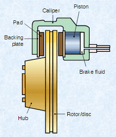
Piston force required (Disk brake system)

jsg94
Messages
8
Reaction score
0
Hello everyone,

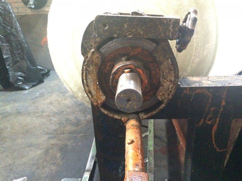
I'm currently working on a project where we need to change the little manual wheel (shown by red arrow) and replace it by a cylinder (either pneumatic or hydraulic). Right now, when the manual wheel is adjusted by rotating it to the right, the contracting rim will come closer together, which slows down the shaft that is rotating the white fabric seen in the image. What I'm trying to figure out is how to calculate the output force needed by the piston in order to successfully bring the contracting rim closer together.

I was looking for some ideas and I found the second image in this PDF (page 6) https://www3.nd.edu/~manufact/FME_pdf_files/FME3_Ch18.pdf . The rims are not in the same location, but I guess that gives you an idea of what I'm looking for. I attached a third image just in case.

I would really appreciate any ideas and general equations to estimate de force required by the piston, so I can select one with the right force range.

Thank you in advance for your help!
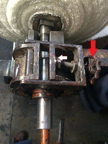
Photo Jul 22, 11 06 23 AM.jpg


Disk brakes.PNG


Photo Jul 22, 11 31 38 AM.jpg
 
Last edited by a moderator:
on Phys.org
jack action said:
You show a disc brake, but you seem to have a band brake or a block/shoe brake.

I attached a small 30 sec video for better reference. What do you think? Block/shoe?
Thank you so much for your time.

https://player.vimeo.com/video/175896622
 
It looks like a block/shoe, but I can't see much. If you want to make some calculations, you will have to take it apart to get measurements. It must be relatively easy because I would guess it should be done regularly for maintenance.

Another (easier) way would be to measure the required force directly. You could also just measure the torque needed to turn the wheel and you can convert this to the applied force (quick estimate, detailed calculations).
 
  • Like
Likes   Reactions: Ketch22
Jack's recommend to calculate using the torque on the existing screw is a good one. If you are replacing the screw with a piston type actuator the hydraulic side of the piston will be pressure adjustable to fine tune the braking required. As long as the piston is of adequate size to provide close to the correct effort the rest will come afterwards.
 
jack action said:
It looks like a block/shoe, but I can't see much. If you want to make some calculations, you will have to take it apart to get measurements. It must be relatively easy because I would guess it should be done regularly for maintenance.

Another (easier) way would be to measure the required force directly. You could also just measure the torque needed to turn the wheel and you can convert this to the applied force (quick estimate, detailed calculations).

Thank you for those links. I didn't think about considering the screw torque before, that is a good idea!

I was doing some additional research and it occurred to me to take a look at my "Machine Elements in Mechanical Design" book by Robert L. Mott. I didn't have access to it during the week, so I had to wait until this weekend to read it. Anyways, there's a chapter on Clutches and Brakes and I found a brake similar to the one I'm working on but without the solenoid (I attached a picture from the book), and instead of the spring I have the screw which I'm looking to replace with a piston. They describe it as a long shoe drum brake. I also attached the section of the chapter that covers that topic.

I'll take some measurements tomorrow and I'll let you know the approach we take!

Thank you again.
 

Attachments

Ketch22 said:
Jack's recommend to calculate using the torque on the existing screw is a good one. If you are replacing the screw with a piston type actuator the hydraulic side of the piston will be pressure adjustable to fine tune the braking required. As long as the piston is of adequate size to provide close to the correct effort the rest will come afterwards.

It is indeed a good idea to consider the torque on the screw. Although, I was looking at a slightly different approach. I attached the files that explain it in my previous reply if you want to take a look at those :) And yes, we do need to adjust the pressure so I've been looking for proportional valves that receive a signal range from 4 to 20 mA, so the input current will be proportional to the output pressure exerted by the piston.
 
Have you considered turning the screw using a motor/gearbox combination? If you can estimate how much torque it takes to turn the wheel, you can likely find a motor with a gearbox that could turn it for you...
 

Similar threads

Replies
3
Views
2K
  • · Replies 8 ·
Replies
8
Views
3K
  • · Replies 15 ·
Replies
15
Views
7K
Replies
58
Views
10K
Replies
23
Views
3K
  • · Replies 8 ·
Replies
8
Views
2K
  • · Replies 13 ·
Replies
13
Views
18K
  • · Replies 3 ·
Replies
3
Views
2K
  • · Replies 14 ·
Replies
14
Views
12K
  • · Replies 16 ·
Replies
16
Views
2K