Power screw design for tensile specimen

  • Thread starter Saladsamurai
  • Start date
  • Tags Tags
    Power Screw
1 reply · 6K views · last reply
Saladsamurai
Messages
3,009
Reaction score
7
I was reading through some examples in my Design text when I came across this one.
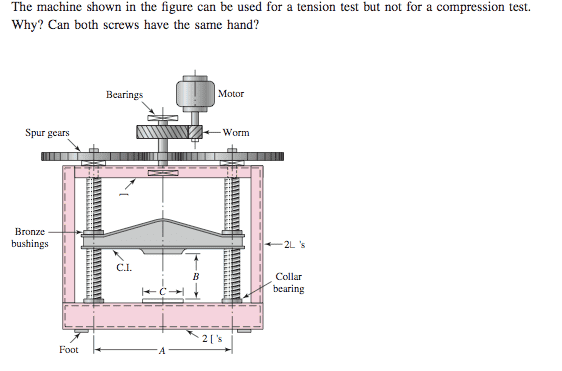
Engineering diagram of a screw-driven test frame with a motor and worm gear driving two spur gears that turn vertical power screws, a bronze bushing and collar bearing, a C.I. crossbar, and labeled dimensions 2L, 2L's, B, C and A with a Foot at the base.
This was their solution:

Printed text excerpt on power screw design: collar (thrust) bearings must bear on the collars, the bottom screw segment must be in compression, tension specimens and grips must be in tension, and both screws must be same-hand threads.


I am not sure that I completely follow it. Can someone help shed some light on what's going on here?

I am assuming that the specimen to be put under tension goes where the "B" dimension is right?
 
Yes, the tensile specimen goes where the B dimension is. Both screws must have the same hand. My impression is, their explanation is very poorly written. Here is the answer I arrived at before reading their solution. The machine is missing thrust bearings at the top of the screws. Therefore, the machine should not be used for a compression test, because galling of the upper channel web material might occur. Plus, the diagram shows only a small-diameter shank inside the upper channel.
