Q:Hydrostatic Pressure vs. Energy Conservation Equation

21 replies · 3K views · last reply
tracker890 Source h
Messages
90
Reaction score
11
Homework Statement
To determine P2
Relevant Equations
hydrostatic pressure and energy conservation equation.
Please help me to understand which ans is correct.
Sketch of a vertical pipe carrying water downward with red arrows, points 1 and 2 marked in blue, vertical height h between them, a side branch with water not flowing, and Q labelled steady flow at the bottom outlet.
To determine the ##P2##.
$$
h_{LM}\ne 0
$$

Method 1:
$$dP=\frac{\partial P}{\partial x}dx+\frac{\partial P}{\partial y}dy+\frac{\partial P}{\partial z}dz$$$$\phantom{\rule{0ex}{0ex}}\rho \overset\rightharpoonup{a}=-\triangledown p+\rho \overset\rightharpoonup{g}\phantom{\rule{0ex}{0ex}}$$$$\triangledown P=\rho (\overset\rightharpoonup{g}-\overset\rightharpoonup{a})$$$$\because steady flow \therefore \overset\rightharpoonup{a}=0$$$$\therefore \triangledown P=\rho \left(\overset\rightharpoonup{g}\right)$$$$\therefore\triangledown P=\rho\left(\overset\rightharpoonup g\right)=\left\langle0,0,-g\right\rangle=\frac{\partial P}{\partial x}dx+\frac{\partial P}{\partial y}dy+\frac{\partial P}{\partial z}dz$$$$dp=-\rho gdz=-\gamma _wdz$$
$$P2=P1+\gamma _wh...........\left( ans1 \right)$$
$$////////////////////////////////////$$
Mtheod 2:
Energy Conservation Equation.$$\frac{{P}_{1}}{\gamma }+\frac{{{V}_{1}}^{2}}{2g}+{Z}_{1}=\frac{{P}_{2}}{\gamma }+\frac{{{V}_{2}}^{2}}{2g}+{Z}_{2}+{h}_{LM}$$$$
Q=AV_1=AV_2\
$$
$$
\therefore V_1=V_2
$$
$$
\therefore \frac{P_1}{\gamma _w}+Z_1=\frac{P_2}{\gamma _w}+Z_2+h_{LM}
$$
$$
\frac{P_2}{\gamma _w}=\frac{P_1}{\gamma _w}+Z_1-Z_2-h_{LM}
$$
$$
P_2=P_1+\gamma _w\left( Z_1-Z_2 \right) -\gamma _w\left( h_{LM} \right)
$$
$$
\ \ =P_1+\gamma _w\left( h \right) -\gamma _w\left( h_{LM} \right) ................\text{(ans2)}
$$
 
Attachments
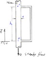
  • Hand-drawn schematic of a vertical pipe carrying water downward with steady flow Q, showing points 1 and 2 separated by height h, a side branch of diameter d, and a datum level marked by z.
    1671098674611.png
    11.8 KB · Views: 183
Last edited:
If water isn’t flowing in the side branch, the differential pressure across 1-2 is 0. So what does that imply about the head loss given the change in elevation?
 
erobz said:
If water isn’t flowing in the side branch, the differential pressure across 1-2 is 0. So what does that imply about the head loss given the change in elevation?
Energy loss is the loss caused by friction in the intermediate pipeline as the fluid flows through the pipe.
 
tracker890 Source h said:
Energy loss is the loss caused by friction in the intermediate pipeline as the fluid flows through the pipe.
Yeah, I get that. If there is viscous loss in the pipe, then for steady flow method 2 is correct. What is the question? I suspect you are supposed to determine ##h_{LM}##?

If that is the case, like I said. The differential pressure across 1-2 is 0. That has implications for the head loss from 1-2, given the change in elevation from 1-2.
 
Last edited:
erobz said:
Yeah, I get that. If there is viscous loss in the pipe, then for steady flow method 2 is correct. What is the question? I suspect you are supposed to determine ##h_{LM}##?

If that is the case, like I said. The differential pressure across 1-2 is 0. That has implications for the head loss from 1-2, given the change in elevation from 1-2.
So, if there is frictional loss in the pipe flow, then
##
\rho \overset{\rightharpoonup}{a}=-\triangledown p+\rho \overset{\rightharpoonup}{g}
##
is not true?
 
tracker890 Source h said:
So, if there is frictional loss in the pipe flow, then
##
\rho \overset{\rightharpoonup}{a}=-\triangledown p+\rho \overset{\rightharpoonup}{g}
##
is not true?
When you are diving into this kind of analysis, I'm on very thin ice. But, if there is viscous loss, there is shear stress acting on the fluid element.

There is no shear "force term" in what you have presented?
 
tracker890 Source h said:
So, if there is frictional loss in the pipe flow, then
##
\rho \overset{\rightharpoonup}{a}=-\triangledown p+\rho \overset{\rightharpoonup}{g}
##
is not true?
this equation omits the viscous friction term.
 
erobz said:
If water isn’t flowing in the side branch, the differential pressure across 1-2 is 0.
This is not correct. $$\Delta P=\rho g\Delta z$$
 
Chestermiller said:
This is not correct. $$\Delta P=\rho g\Delta z$$
But the following formula is established.
why?
Handwritten annotated Navier-Stokes equation in cylindrical coordinates with red-highlighted terms, and a handwritten hydrostatic result below reading grad p = rho g and dp = -rho g dz.
 
Chestermiller said:
##V_z## is a function of r.
so Vz profile is,
Hand-drawn schematic of a vertical pipe carrying steady water flow downward, with points 1 and 2 marked at its top and lower section, a manometer tube attached on the right labelled water not flowing, height h and offset d marked, and red velocity profile arrows drawn across the pipe.
 
Chestermiller said:
This is not correct. $$\Delta P=\rho g\Delta z$$
We are getting contradiction somehow?

In the main applying COE:

##v_1 = v_2##
##z_2 = 0## elevation datum

$$ \frac{P_2}{\gamma} = \frac{P_1}{\gamma} + z_1 - \sum_{1 \to 2} h_L$$

Where, ##\sum_{1 \to 2} h_L > 0##

Applying COE across the branch:

##v_1 = v_2 = 0##
## \sum_{1 \to 2} h_L = 0 ##

$$ \frac{P_2}{\gamma} = \frac{P_1}{\gamma} + z_1 $$

?

For parallel sections the loss ## h_{main} = h_{branch}##

We also have to satisfy continuity.
 
Last edited:
  • Like
Likes   Reactions: tracker890 Source h
erobz said:
We are getting contradiction somehow?

In the main applying COE:

##v_1 = v_2##
##z_2 = 0## elevation datum

$$ \frac{P_2}{\gamma} = \frac{P_1}{\gamma} + z_1 - \sum_{1 \to 2} h_L$$

Where, ##\sum_{1 \to 2} h_L > 0##

Applying COE across the branch:

##v_1 = v_2 = 0##
## \sum_{1 \to 2} h_L = 0 ##

$$ \frac{P_2}{\gamma} = \frac{P_1}{\gamma} + z_1 $$

?

For parallel sections the loss ## h_{main} = h_{branch}##

We also have to satisfy continuity.
$$
I\ think\ h_{LM}\ne 0\ is\ not\ correct\ in\ this\ example,\ h_{LM}\ne 0\ must\ be\ changed\ to\ h_{LM}=0.
$$
 
My belief is the contradiction is hidden in the assumption of the problem statement, that the flow in the side branch is 0.

If you apply COE (using what I shown above) without invoking the "no flow" condition in the branch the following is the system of equations:

$$ \frac{P_2}{\gamma} = \frac{P_1}{\gamma} + z_1 - \sum_{1 \to 2} h_{L_m}$$

$$ \frac{P_2}{\gamma} = \frac{P_1}{\gamma} + z_1 - \sum_{1 \to 2} h_{L_{b}}$$

That system reduces to the established result:

$$ \sum_{1 \to 2} h_{L_m} = \sum_{1 \to 2} h_{L_b}$$

$$ k_{m} \frac{Q_{m}^2}{A_{m}^2 2g } = k_{b} \frac{Q_{b}^2}{A_{b}^2 2g }$$

Let the total flow into the node be known and equal to ##Q##. It follows that:

$$ k_{m} \frac{(Q - Q_b)^2}{A_{m}^2} = k_{b} \frac{Q_{b}^2}{A_{b}^2}$$

$$ \implies Q^2 - 2 Q Q_b + \left( 1 - \left( \frac{A_m}{A_b} \right)^2 \frac{k_b}{k_m} \right) Q_b^2 = 0 $$

I get the following solution:

$$ Q_b = Q \left( \frac{1+ \frac{A_m}{A_b} \sqrt{ \frac{k_b}{k_m} } }{ 1 - \left( \frac{A_m}{A_b} \right)^2 \frac{k_b}{k_m} } \right)$$

So if you take ##k_m, A_m > 0## you shouldn't find ## Q_b \to 0 ##, unless ##Q = 0##, or in the limit as ## k_b \to \infty, A_b \to 0 ##.
 
Last edited:
  • Like
Likes   Reactions: tracker890 Source h
For laminar flow, the force balance ;on the fluid between points 1 and 2 reads:
$$P_1\left(\frac{\pi D^2}{4}\right)+\rho\left(\frac{\pi D^2}{4}\Delta z \right)g=P_2\left(\frac{\pi D^2}{4}\right)+\tau_w(\pi D \Delta z) $$where ##\tau_w## is the viscous shear stress at the wall: $$\tau_w=\left(\frac{32Q}{\pi D^3}\right)\eta$$where Q is the downward volumetric flow rate and ##\eta## is the viscosity. What does this give you when you divide both sides of the first equation by ##\left(\frac{\pi D^2}{4}\right)## and substitute the 2nd equation?
 
Chestermiller said:
For laminar flow, the force balance ;on the fluid between points 1 and 2 reads:
$$P_1\left(\frac{\pi D^2}{4}\right)+\rho\left(\frac{\pi D^2}{4}\Delta z \right)g=P_2\left(\frac{\pi D^2}{4}\right)+\tau_w(\pi D \Delta z) $$where ##\tau_w## is the viscous shear stress at the wall: $$\tau_w=\left(\frac{32Q}{\pi D^3}\right)\eta$$where Q is the downward volumetric flow rate and ##\eta## is the viscosity. What does this give you when you divide both sides of the first equation by ##\left(\frac{\pi D^2}{4}\right)## and substitute the 2nd equation?
It gives me two different results for ##P_2## depending on which branch I take in going from ##1 \to 2##.

In the OP ##Q_m>0## in the main and in the branch ##Q_b = 0##. I don't care what flow regime we are working in, that is an issue.

The faulty assumption in the problem statement leading to the contradiction is that ##Q_b = 0##.
 
Last edited:
erobz said:
It gives me two different results for ##P_2## depending on which branch I take in going from ##1 \to 2##.

In the OP ##Q_m>0## in the main and in the branch ##Q_b = 0##. I don't care what flow regime we are working in, that is an issue.

The faulty assumption in the problem statement leading to the contradiction is that ##Q_b = 0##.
Yes. That's right. It only works out if the fluid is inviscid.
 
  • Like
Likes   Reactions: tracker890 Source h
tracker890 Source h said:
I think ##h_{LM}\ne 0## is not correct in this example,##h_{LM}\ne 0## must be changed to ##h_{LM}=0##.
I fixed your Latex a bit. ( don't put back slash unless its introducing a special function like "\sin" or "\frac{}{}" and the delimiters "##" put code inline with text "$$" give it its own line centered justified)

The problem is, if you make the fluid inviscid then then the flow is split evenly between each branch (regardless of branch dimension)?

Inviscid flow and multi branch analysis don't mix.
 
erobz said:
I fixed your Latex a bit. ( don't put back slash unless its introducing a special function like "\sin" or "\frac{}{}" and the delimiters "##" put code inline with text "$$" give it its own line centered justified)

The problem is, if you make the fluid inviscid then then the flow is split evenly between each branch (regardless of branch dimension)?

Inviscid flow and multi branch analysis don't mix.
For viscous flow, the flow in the branch is related to the flow in the main channel by $$Q_B=\left(\frac{D_B}{D}\right)^4Q$$So, for a diameter ratio of 0.1, the flow ratio is 0.0001.
 
  • Like
Likes   Reactions: tracker890 Source h