Mech_LS24
- 148
- 16
- Homework Statement
- The robot arm is driven by two hydraulic cilinders A and B which brings point D rotates CW. The gear in point D has a angular velocity of 5 rad/s. Calculate the velocity and acceleration of the part in point C.
- Relevant Equations
- Velocity = angular velocity * radius
Acceleration = angular velocity^2 * radius
Hello,
Given the figure below, and the following statement:
"The robot arm is driven by two hydraulic cilinders A and B which brings point D rotates CW. The gear in point D has a angular velocity of 5 rad/s. Calculate the velocity and acceleration of the part in point C."
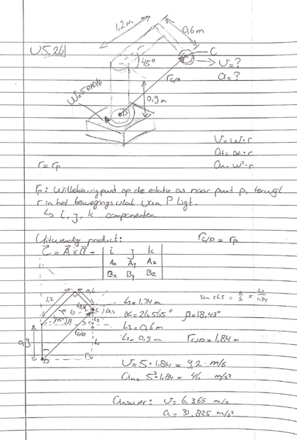
First I determined the distance from point D to C as rc/d, this distance is used for the formula's. The answer doesn't correspond, what am I missing here??
Like to here! :)
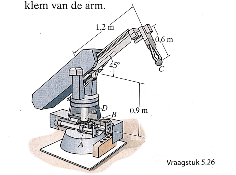
Given the figure below, and the following statement:
"The robot arm is driven by two hydraulic cilinders A and B which brings point D rotates CW. The gear in point D has a angular velocity of 5 rad/s. Calculate the velocity and acceleration of the part in point C."
First I determined the distance from point D to C as rc/d, this distance is used for the formula's. The answer doesn't correspond, what am I missing here??
Like to here! :)
