s-parameter mathematical theory for crosstalk analysis

  • Thread starter yefj
  • Start date
5 replies · 2K views · last reply
yefj
Messages
165
Reaction score
2
Hello, I have a system shown in the photo .I have S-parameters of this system there are several tests like
1.integrated crosstalk noise which uses victim S-params near end and far end cross talk
2.PSXT (power sum cross talk)
3.MDNEXT(multi distributed NEXT)
4.Normalized MDNEXT.
Is there some theory or even better a code which takes VNA s-param data and shows how its been calculated exactly based on the S-params?
 
Attachments
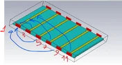
  • Diagram of a multi-conductor PCB trace structure with several parallel yellow traces on a teal substrate, red ports numbered 1, 3, 5, 7, 9 and 11 along the edges, and blue arrows marking connections between ports.
    NEXT.webp
    39.3 KB · Views: 24
I did a Google search on deriving NEXT from s-parameters and got some good hits (videos and articles). Maybe try that same search to see if you find some useful resources...

Screenshot of a Google search for "deriving NEXT from s-parameters" showing an AI Overview with a small plot of a dip-shaped curve and a yellow waveform labelled S31, beside a list of related article results.
 
Hello , I did google too before posting they dont show exact matematical manual to derive it.
Is there some recoomended manual I could use?
 
Hello berkerman, power sum Next is defined as shown below by the attached article.
is there some mathematical expression for these terms?
1.MDNEXT(multi distributed NEXT)
2.Normalized MDNEXT.
Printed page with two equations for Power Sum NEXT in dB: Power Sum NEXT = 10 log10 of the sum from i=1 to n of 10 to the power of minus NEXT_i over 10, and NEXT_PS = -10 log of (10 to the power of minus NEXT_1 over 10, plus 10 to the power of minus NEXT_2 over 10, plus 10 to the power of minus NEXT_3 over 10), with variable definitions beneath.
 
Attachments
UPDATE:
Hello , I have found the defintion of ICN as shown below in photo and attached document.
The first one is integrated cross talk noise,my victim is line 1->2.
Next is the coulping from near aggressor lines.
S31 S51 S71
NL0 is the coupling from port 3 to 1 ,S31
NL1 is the coupling from port 5 to 1 ,S51
NL2 is the coupling from port 7 to 1 ,S71

I simulated my 4 lines 0.01GHz to 67GHz .
given the last photo of A_nt f f_nt f_r f_b in equation 12-12 of the photo below
What are they in my case?

What is delta_f in 12-14 equation in my case ?
Thanks.

https://www.oiforum.com/wp-content/uploads/2019/01/OIF_CEI_03.1.pdf
3D render of four parallel coupled microstrip lines on a dielectric substrate, with red port markers numbered 1 to 8 at the line ends and a bounding box around the structure.

Page 12.2.1.2 Integrated crosstalk noise: text on MDNEXT and MDFEXT loss, with Equation 12-10 MDNEXT_loss(f) = -10 x log10(sum over all NEXTs of 10^(-(NLi(f))/10)) dB, for 0.05 GHz to fb.

Equations 12-12 and 12-13 defining transmit and receive weighting functions W_nt(f) and W_ft(f) with sinc-squared and rise-time filter terms, followed by equations 12-14 and 12-15 for near-end and far-end integrated crosstalk noise.