Found this paper
https://ieeexplore.ieee.org/document/1284886
also accessible here without login:
https://www.researchgate.net/public...neration_of_Magnetic_Fields_Using_Loop_Probes
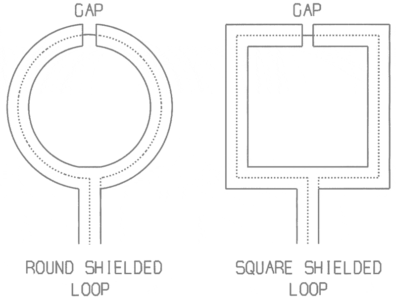
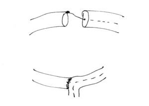
If they are right, then there can be situations where Fig (B) in my question could actually make sense. A key point they assert is that if the diameter is not negligible compared to wavelength, then the outer conductor can't be regarded as a short, nor is it really working as a shield -- it is actually part of the pickup structure. So if your aim is to minimize common mode noise then symmetry is the key. The loop has to be designed to work as a balun as well as a pickup loop.
I realized also that there are different scenarios with different goals, for example:
(1) The probe signal is well above our amplifier's noise floor, the instrumentation itself doesn't produce much common mode noise, and we want to isolate the magnetic field from electrical fields near the probe. Example: probing currents and magnetics around a switched power supply circuit.
(2) The probe signal is quite weak, and our equipment (e.g. computer) emits common mode interference into the feed line. Example: a shortwave loop antenna connected to an SDR receiver which is connected to a computer via USB.
My interest happens to be focused on scenario (2) where you can't really have diameter <<<< wavelength because then the signal would be below the amplifier/SDR's noise floor. In this case symmetry is important, and Fig (B) can have some merit.