The multimeter is not displaying mv of strain gauge in circuit

  • Context: Undergrad 
  • Thread starter Thread starter Micheal_Leo
  • Start date Start date
  • Tags Tags
    Multimeter Strain gauge
Click For Summary

Discussion Overview

The discussion revolves around troubleshooting a Wheatstone bridge circuit with a strain gauge, focusing on issues related to multimeter readings, circuit configuration, and voltage supply. Participants explore various technical aspects, including resistor values, voltage levels, and connections to an HX711 A-D converter.

Discussion Character

  • Technical explanation
  • Debate/contested
  • Mathematical reasoning
  • Experimental/applied

Main Points Raised

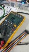
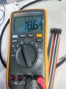
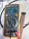
  • One participant reports that their multimeter is not displaying any readings from the Wheatstone bridge circuit and seeks guidance.
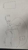
  • Another participant suggests switching the multimeter to DC volts to check the voltage and requests details about the circuit and resistor values.
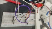
  • Concerns are raised about the matching of resistor ratios in the Wheatstone bridge, with a recommendation to replace a 220 ohm resistor with a 120 ohm resistor to achieve proper balance.
  • Participants discuss using series resistors as a substitute for the missing 120 ohm resistor.
  • There are questions about the appropriateness of the bias voltage being used, with suggestions to lower it to conserve power.
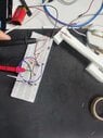
  • A participant notes that they observe changes in mV readings when flexing the strain gauge but also experiences issues with overheating due to high voltage, leading to erratic readings.
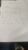
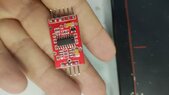
  • There are recommendations to use a lower voltage supply and to utilize the HX711's built-in voltage regulator for the bridge circuit.
  • One participant mentions the importance of maintaining a ratiometric relationship between the bridge drive voltage and the A-D converter for accurate measurements.
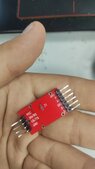
  • Another participant suggests using the HX711 due to its availability and cost-effectiveness, while also seeking guidance on connecting the Wheatstone bridge to the HX711.
  • Clarifications are provided regarding the connections on the HX711 PCB and references to the datasheet for proper wiring.

Areas of Agreement / Disagreement

Participants express various views on the appropriate resistor values, voltage levels, and circuit configurations. There is no consensus on the best approach, and multiple competing suggestions are presented throughout the discussion.

Contextual Notes

Participants mention limitations related to available components and resources, which may affect their circuit design choices. There are also unresolved questions regarding the optimal voltage supply and the specific connections to the HX711.

Who May Find This Useful

Individuals working with strain gauges, Wheatstone bridge circuits, or the HX711 A-D converter may find this discussion relevant, particularly those troubleshooting similar issues in their setups.

Micheal_Leo
Messages
103
Reaction score
4
i have made the wheatstone bridge( 3 resistors and 1 strain gauge) circuit but multimiter is not displaying anything , please need guide
 

Attachments

  • h1.jpg
    h1.jpg
    43.5 KB · Views: 131
  • h2.jpg
    h2.jpg
    35.8 KB · Views: 139
  • h3.jpg
    h3.jpg
    42.5 KB · Views: 108
Physics news on Phys.org
Micheal_Leo said:
... but multimiter is not displaying anything ...
You have an overload on the mV scale. Switch to DC volts to see what voltage you have.

Please provide the circuit you are using with all resistor values.
What is the resistance of the strain gauge?
 
  • Like
Likes   Reactions: Micheal_Leo
Baluncore said:
You have an overload on the mV scale. Switch to DC volts to see what voltage you have.
Please provide the circuit you are using with all resistor values.
What is the resistance of the strain gauge?

please find the attached schematic diagram
 

Attachments

  • wx_camera_1690883390131.jpg
    wx_camera_1690883390131.jpg
    12.8 KB · Views: 122
Last edited by a moderator:
The resistor ratios must match.
Is that a pair of 220R = 220 ohm resistors in the top row, making half the supply ?

Below left is another 220R resistor, but it should match the 120 ohm strain gauge, so it also makes about half the supply. Then mV range should work.

Replace the bottom left 220R with a 120R resistor.
 
Baluncore said:
The resistor ratios must match.
Is that a pair of 220R = 220 ohm resistors in the top row, making half the supply ?

Below left is another 220R resistor, but it should match the 120 ohm strain gauge, so it also makes about half the supply. Then mV range should work.

Replace the bottom left 220R with a 120R resistor.
yes half supply,i do not have 120 ohm resistors,.can i use 100+ 22 ohm resistors in series?
 
Micheal_Leo said:
please find the attached schematic diagram
Why are you using such a high bias voltage? Maybe switch to a single 1.5V AA battery to avoid wasting so much power...
 
berkeman said:
Why are you using such a high bias voltage? Maybe switch to a single 1.5V AA battery to avoid wasting so much power...

actually i have limited resources so have to do in limit resource
 
Last edited by a moderator:
Micheal_Leo said:
yes half supply,i do not have 120 ohm resistors,.can i use 100+ 22 ohm resistors in series?
Yes.
 
Baluncore said:
Yes.
THE Attached results are mv and Voltage , please see this , i will connect it to hx711, these results before force not applied , please guide that should i consider mv or voltage to transfer it to arduino to study stress in that part.the PLA printing material not follow hookes law i have applied force on part for testing so little bending is present in part
 

Attachments

  • Weixin Image_20230802140610.jpg
    Weixin Image_20230802140610.jpg
    41.4 KB · Views: 105
  • Weixin Image_20230802140602.jpg
    Weixin Image_20230802140602.jpg
    42.5 KB · Views: 140
  • Weixin Image_20230802141542.jpg
    Weixin Image_20230802141542.jpg
    26.9 KB · Views: 141
  • #10
I do not know where you are going with this.
Do you see any change in the mV reading when you flex the strain gauge?

If you see only a small change, you may need to adjust the 22R resistor, to better balance the bridge, to get closer to a zero difference voltage output. Then you can use more gain in the hx711 without the amplified DC offset hitting the voltage limits.

The differential voltage output that now goes to your mV meter, will go to the hx711 differential inputs, INA+, INA-. The bridge drive voltage will probably come from the hx711, AVDD and AGND.
 
  • #11
Baluncore said:
I do not know where you are going with this.
Do you see any change in the mV reading when you flex the strain gauge?

If you see only a small change, you may need to adjust the 22R resistor, to better balance the bridge, to get closer to a zero difference voltage output. Then you can use more gain in the hx711 without the amplified DC offset hitting the voltage limits.

The differential voltage output that now goes to your mV meter, will go to the hx711 differential inputs, INA+, INA-. The bridge drive voltage will probably come from the hx711, AVDD and AGND.
i see change in mv but also my finger burn accidently comes near to strain gauge , strain gauge get hot during this phenomena mv voltage out of control like it kept increasing ,

should i give 5V , right now i am giving 9V
 
  • #12
Micheal_Leo said:
... i see change in mv but also my finger burn accidently comes near to strain gauge ...
Too much voltage to the bridge circuit.
Too much bridge current.
Too much heating of the strain gauge resistance.
The gauge resistance is temperature dependent, so balance changes.
Use less voltage, use AVDD and AGND from the hx711.
 
  • Like
Likes   Reactions: Micheal_Leo
  • #13
Baluncore said:
Too much voltage to the bridge circuit.
Too much bridge current.
Too much heating of the strain gauge resistance.
The gauge resistance is temperature dependent, so balance changes.
Use less voltage, use AVDD and AGND from the hx711.
thank you very much, hx711 supplying voltage is 5v, i shoud use dc power supply and give 1.5v to both hx711 and wheatstone brdige
 
  • #14
The hx711 can run on between 3 and 5 V. If you use the same voltage as your controller, the digital signal voltages will all match without problems.

The hx711 has a regulator that provides the voltage drive to the bridge. The voltage is set by the ratio of R1 and R2 on the hx711 reference PCB design in the data sheet. Use what it has now, or select resistors that set the bridge voltage to somewhere between 1.2 and 2.5 volts.
 
  • Like
Likes   Reactions: Micheal_Leo
  • #15
Baluncore said:
The hx711 can run on between 3 and 5 V. If you use the same voltage as your controller, the digital signal voltages will all match without problems.

The hx711 has a regulator that provides the voltage drive to the bridge. The voltage is set by the ratio of R1 and R2 on the hx711 reference PCB design in the data sheet. Use what it has now, or select resistors that set the bridge voltage to somewhere between 1.2 and 2.5 volts.
i have voltage regulator so have intention to supply 3v to both bridge and hx711
 
  • #16
Micheal_Leo said:
i have voltage regulator so have intention to supply 3v to both bridge and hx711
If you increase the bridge drive voltage by 1%, you get a 1% increase in the difference voltage from the bridge, for the same strain. That is a problem with accurate 24 bit measurements.

The A-D converter is ratiometric. It uses the bridge drive voltage as a full-scale reference, and so automatically corrects for variations. That is why it has the voltage regulator for the bridge drive on the same chip as the A-D converter. If you do not use that on-chip regulator, you will get scale errors in the strain readings. Read the data sheet, and follow the advice.
 
  • Like
Likes   Reactions: berkeman
  • #17
Baluncore said:
If you increase the bridge drive voltage by 1%, you get a 1% increase in the difference voltage from the bridge, for the same strain. That is a problem with accurate 24 bit measurements.

The A-D converter is ratiometric. It uses the bridge drive voltage as a full-scale reference, and so automatically corrects for variations. That is why it has the voltage regulator for the bridge drive on the same chip as the A-D converter. If you do not use that on-chip regulator, you will get scale errors in the strain readings. Read the data sheet, and follow the advice.
please can you suggest best A-D converter
 
  • #18
Micheal_Leo said:
please can you suggest best A-D converter
You cannot afford the best.
Use the hx711, because it is available, cheap ($2), and comes mounted on a PCB.
 
  • Like
Likes   Reactions: Micheal_Leo
  • #19
Baluncore said:
You cannot afford the best.
Use the hx711, because it is available, cheap ($2), and comes mounted on a PCB.
i have try to do it , somehow it work as i expected , the video attached , secondly the follwoing hx711 amplifier i have , i am very much confused how to attach wheatstone bridge with this hx711 , please need your guidance

video about strain gauge and wheatstone bridge

i have try to draw diagram of connecting , please check
 

Attachments

  • Weixin Image_20230803090826.jpg
    Weixin Image_20230803090826.jpg
    31 KB · Views: 121
  • Weixin Image_20230803090833.jpg
    Weixin Image_20230803090833.jpg
    19.9 KB · Views: 111
  • gt.jpg
    gt.jpg
    16.7 KB · Views: 147
Last edited:
  • #20
I think, in the Weixin picture, at the analogue end of the PCB ...
A+ and A- are the bridge output terminals, (your old meter connections).
GND is probably analogue ground to the bridge.
Out+ is the regulated power to the bridge.
You can check those by following the terminals to the chip pins.

Do you have a copy of the hx711 data sheet?
It shows the connections to the bridge on page 1, fig 1. Also page 6, fig 4.
https://cdn.sparkfun.com/datasheets/Sensors/ForceFlex/hx711_english.pdf
 

Similar threads

  • · Replies 77 ·
3
Replies
77
Views
6K
  • · Replies 3 ·
Replies
3
Views
3K
  • · Replies 1 ·
Replies
1
Views
1K
  • · Replies 2 ·
Replies
2
Views
683
  • · Replies 2 ·
Replies
2
Views
3K
  • · Replies 3 ·
Replies
3
Views
2K
  • · Replies 13 ·
Replies
13
Views
2K
  • · Replies 9 ·
Replies
9
Views
3K
  • · Replies 1 ·
Replies
1
Views
2K
  • · Replies 14 ·
Replies
14
Views
6K