How to connect this strain gauge?

  • #1
Micheal_Leo
63
4
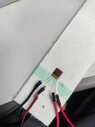
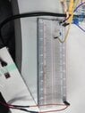
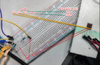
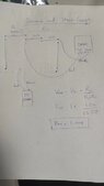
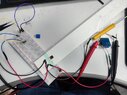
recently i bought this strain guage where vender said it is 4bridge, i am not sure how to connect this in wheatstone bridge , i have 120 ohms resistors, and 120ohm strain gauge.
please need guide thank you.
Screenshot_2023-08-23-03-13-10-858_com.xunmeng.pinduoduo-edit.jpg
 
Last edited by a moderator:
Engineering news on Phys.org
  • #2
From the look of the image, I get the impression that those four areas are actually the four resistor elements of a bridge. Put volts across two terminals and measure the volts across the other pair, which should be around Zero with the gauge undistorted and balanced. Do you have a data sheet?
 
  • Like
Likes Micheal_Leo
  • #3
sophiecentaur said:
From the look of the image, I get the impression that those four areas are actually the four resistor elements of a bridge. Put volts across two terminals and measure the volts across the other pair, which should be around Zero with the gauge undistorted and balanced. Do you have a data sheet?
thank you for reply, they did not have anything, from internet i found this
Screenshot_2023-08-23-04-28-23-696_com.android.chrome-edit.jpg
 
Last edited by a moderator:
  • #4
Looks ok to me. Wire it up and hit it with about 5V (arbitrary) and see what happens.
 
  • Like
Likes Tom.G
  • #5
sophiecentaur said:
Looks ok to me. Wire it up and hit it with about 5V (arbitrary) and see what happens.
i have AD620 FOR AMPLIFICATION, i connect strain guage with breadboard and arduino to get voltage output from arduino, arduino is not showing anything, please can you see the specimen principal stress direction and strain gauge orientation and selection
sophiecentaur said:
Looks ok to me. Wire it up and hit it with about 5V (arbitrary) and see what happens.
the strain gauge heat up when supply voltage but reading not coming out from arduino i think i made wrong in orientation starin guage
 

Attachments

  • mmexport1692787100661.jpg
    mmexport1692787100661.jpg
    11 KB · Views: 62
  • IMG_20230823_183349.jpg
    IMG_20230823_183349.jpg
    36.2 KB · Views: 57
  • #6
The voltage to the bridge power supply terminals need only be about 1 volt.
For a healthy symmetrical bridge, the resistance between the two signal output terminals, should be the same as the resistance between the two power terminals. If that is not the case, then the bridge has been damaged.
 
  • Informative
  • Like
Likes Micheal_Leo and sophiecentaur
  • #7
Baluncore said:
The voltage to the bridge power supply terminals need only be about 1 volt.
For a healthy symmetrical bridge, the resistance between the two signal output terminals, should be the same as the resistance between the two power terminals. If that is not the case, then the bridge has been damaged.
but AD620 AMPLIFIER NEED 3-11VOLTAGE, I have supplied 3 voltage to both( strain guage and amplifier), does my strain gauge orientation and principal stress direction same?
 
  • #8
Three volts should be OK, but heating the gauge can be a problem with higher voltages.

In an earlier picture, I see the strain gauge is glued onto a white structure. Maybe the connections you have used, or the orientation, is such that you get cancellation of the resistance changes due to the strain. Can you place the bridge gauge on a square of material for experimentation, until you have the electronics working?
 
  • #9
Baluncore said:
Three volts should be OK, but heating the gauge can be a problem with higher voltages.

In an earlier picture, I see the strain gauge is glued onto a white structure. Maybe the connections you have used, or the orientation, is such that you get cancellation of the resistance changes due to the strain. Can you place the bridge gauge on a square of material for experimentation, until you have the electronics working?
thank you for reply, you mean i print square shape 3D and put new bridge on it?
 
  • #10
Micheal_Leo said:
, you mean i print square shape 3D and put new bridge on it?
No printing required.
Just stick a bridge onto a scrap piece of flat material, something you can bend with your hand while you experiment with the electronics.
 
  • Like
Likes Micheal_Leo
  • #11
Baluncore said:
No printing required.
Just stick a bridge onto a scrap piece of flat material, something you can bend with your hand while you experiment with the electronics.
yes i can do that
 
  • Like
Likes Baluncore
  • #12
Micheal_Leo said:
the strain gauge heat up when supply voltage but reading not coming out from arduino
I guess this could be a generational thing but did you consider using an independent supply and measuring the emerging volts with a DMM? An Arduino may be smart but you can't beat taking measurements in isolation if you don't know how the strain device will behave.
 
  • Like
Likes Micheal_Leo
  • #13
You might want to take another? look at the AD620 datasheet.
 
  • Like
Likes Micheal_Leo
  • #14
Dullard said:
You might want to take another? look at the AD620 datasheet.
Micheal_Leo said:
... but AD620 AMPLIFIER NEED 3-11VOLTAGE, I have supplied 3 voltage to both( strain guage and amplifier), ...
The AD620 requires a minimum of ±2.3 V, that is 4.6 volts total. Depending on the circuit's range of output voltage, you will need more than a 5 volt supply. That will be too high for stable operation of the strain gauge.
 
  • Like
Likes Micheal_Leo
  • #15
Baluncore said:
The AD620 requires a minimum of ±2.3 V, that is 4.6 volts total. Depending on the circuit's range of output voltage, you will need more than a 5 volt supply. That will be too high for stable operation of the strain gauge.
Hence my question about using a DMM as a starter, to see what the gauge actually does. There must be a few mV to measure.
 
  • Like
Likes Micheal_Leo
  • #16
Baluncore said:
No printing required.
Just stick a bridge onto a scrap piece of flat material, something you can bend with your hand while you experiment with the electronics.
vide DC
unfortunately i can not give 1v to bridge , my adapter can not set on 1 v , please guide thank you
 

Attachments

  • Weixin Image_20230825033625.jpg
    Weixin Image_20230825033625.jpg
    22.5 KB · Views: 46
  • #17
Micheal_Leo said:
unfortunately i can not give 1v to bridge , my adapter can not set on 1 v ,
Do you have a soldering iron, by any chance - or perhaps you do your connections on a bread board? Make yourself a potential divider and 'manufacture' 1V that way from the same power supply that you are using for other things.

Edit: and do you have a DMM?
 
  • Like
Likes Micheal_Leo
  • #18
Baluncore said:
No printing required.
Just stick a bridge onto a scrap piece of flat material, something you can bend with your hand while you experiment with the electronics.
vide DC
unfortunately i can not give 1v to bridge , my adapter can not set on 1 v , please guide thank you
sophiecentaur said:
Do you have a soldering iron, by any chance - or perhaps you do your connections on a bread board? Make yourself a potential divider and 'manufacture' 1V that way from the same power supply that you are using for other things.

Edit: and do you have a DMM?
yes i have these

how can i establish potential divider for 1V , thank you
 

Attachments

  • PhF.jpg
    PhF.jpg
    47.1 KB · Views: 50
  • #19
Micheal_Leo said:
how can i establish potential divider for 1V , thank you
You must know know the basics of a potential divider? This link will remind you about the basic potential divider idea. But, for a load of resistance as low as the 120Ω bridge, it may be better use either a low voltage regulator (off the shelf) to give you 1V from your amplifier power supply.
This is very basic circuit stuff and you really should try to learn about it for your future use. It's not really appropriate for me to design your circuits for you. There must be loads of information about interfacing the Arduino with simple devices - even your strain gauge bridge.
 
  • Like
Likes Micheal_Leo
  • #20
sophiecentaur said:
You must know know the basics of a potential divider? This link will remind you about the basic potential divider idea. But, for a load of resistance as low as the 120Ω bridge, it may be better use either a low voltage regulator (off the shelf) to give you 1V from your amplifier power supply.
This is very basic circuit stuff and you really should try to learn about it for your future use. It's not really appropriate for me to design your circuits for you. There must be loads of information about interfacing the Arduino with simple devices - even your strain gauge bridge.
have tried to manage 1V using 2(1.5k) and 10k , i am thinking like this not sure i am right or wrong , appreciate your valuable time and guidance

the out from voltage divider circuit will go to breadboard down relay, and the strain guage + and - will connect to this relay
 

Attachments

  • Weixin Image_20230825060211.jpg
    Weixin Image_20230825060211.jpg
    41.1 KB · Views: 44
  • Weixin Image_20230825060158.jpg
    Weixin Image_20230825060158.jpg
    42.3 KB · Views: 50
  • 2023-08-25_06-07-19.jpg
    2023-08-25_06-07-19.jpg
    68.8 KB · Views: 53
Last edited:
  • #21
Micheal_Leo said:
have tried to manage 1V using 2(1.5k) and 10k , i
Are you using the diagram in the link I quoted? Which is R2 and R1 and what is your supply voltage? Show your working how you calculated 1V out? Your output volts can be obtained by many different values for R2 but consider what happens when you connect the bridge across the output of the potential divider, the resistance ratio changes a lot (current will flow through the bridge). The bridge presents 120Ω and you need to consider this because it appears in parallel with R2 so you need a different R1. Google with "using potential divider to change supply volts" and you'll find loads of discussions which show you what I mean. If you have a box of resistors then your bread board will make this easy to experiment with.
A 1V voltage regulator may be better because the output volts do not depend on the value of the bridge resistance.

PS. I just found your earlier thread on the same topic. It may be just too hard for you and maybe you should try a simpler project first, to get familiar with the basics of electronic circuits. It's all good stuff though and you can progress to this project eventually but not if you are trying to sort out everything at once.
 
  • #22
sophiecentaur said:
Are you using the diagram in the link I quoted? Which is R2 and R1 and what is your supply voltage? Show your working how you calculated 1V out? Your output volts can be obtained by many different values for R2 but consider what happens when you connect the bridge across the output of the potential divider, the resistance ratio changes a lot (current will flow through the bridge). The bridge presents 120Ω and you need to consider this because it appears in parallel with R2 so you need a different R1. Google with "using potential divider to change supply volts" and you'll find loads of discussions which show you what I mean. If you have a box of resistors then your bread board will make this easy to experiment with.
A 1V voltage regulator may be better because the output volts do not depend on the value of the bridge resistance.

PS. I just found your earlier thread on the same topic. It may be just too hard for you and maybe you should try a simpler project first, to get familiar with the basics of electronic circuits. It's all good stuff though and you can progress to this project eventually but not if you are trying to sort out everything at once.
the other possibility to have 1 V as shown by calculation and DMM
 

Attachments

  • DMM.jpg
    DMM.jpg
    43.6 KB · Views: 56
  • VD.jpg
    VD.jpg
    16.2 KB · Views: 55
  • #23
sophiecentaur said:
Are you using the diagram in the link I quoted? Which is R2 and R1 and what is your supply voltage? Show your working how you calculated 1V out? Your output volts can be obtained by many different values for R2 but consider what happens when you connect the bridge across the output of the potential divider, the resistance ratio changes a lot (current will flow through the bridge). The bridge presents 120Ω and you need to consider this because it appears in parallel with R2 so you need a different R1. Google with "using potential divider to change supply volts" and you'll find loads of discussions which show you what I mean. If you have a box of resistors then your bread board will make this easy to experiment with.
A 1V voltage regulator may be better because the output volts do not depend on the value of the bridge resistance.

PS. I just found your earlier thread on the same topic. It may be just too hard for you and maybe you should try a simpler project first, to get familiar with the basics of electronic circuits. It's all good stuff though and you can progress to this project eventually but not if you are trying to sort out everything at once.
I have tried to get reading from wheatstone bridge , the beam not bend just in stationar position , although the reading from DMM not stable ,

Voltage output from wheatstone bridge
Voltage reading from AD620 output
 
  • #24
Micheal_Leo said:
the other possibility to have 1 V as shown by calculation and DMM
That 1.04V looks ok. It will change when you hang the bridge on the output? That's because you have changed the effective value of R2. Starting with that 120Ω, what R1 value is needed to get 1V? Insert new resistor and check that you get 1V.
Connect DMM across the other two terminals of the bridge. You should get low value (zero if perfectly balanced). Flex the bridge and see change in DMM volts
 
  • Like
Likes Micheal_Leo
  • #25
sophiecentaur said:
That 1.04V looks ok. It will change when you hang the bridge on the output? That's because you have changed the effective value of R2. Starting with that 120Ω, what R1 value is needed to get 1V? Insert new resistor and check that you get 1V.
Connect DMM across the other two terminals of the bridge. You should get low value (zero if perfectly balanced). Flex the bridge and see change in DMM volts
several things i confirmed .
1) the voltage is receiving by bridge is 1V
2) the output from wheatstone bridge(DMM) is fluctuating a lot , never stable going to very high value and drop sudden.
3) the voltge in DMM is between 0.004-0.006 , mv fluctuates a lot
 

Attachments

  • mn.jpg
    mn.jpg
    61.8 KB · Views: 53
Last edited:
  • #26
Micheal_Leo said:
1) the voltage is receiving by bridge is 1V
Have you modified your potential divider resistors? If not then there is something wrong with your connections. The ratio of the 'pot' would be 120/10120.
Have you used your DMM to find the resistances between (all) the bridge terminal pairs? What do you get?
 
  • #27
sophiecentaur said:
Have you modified your potential divider resistors? If not then there is something wrong with your connections. The ratio of the 'pot' would be 120/10120.
Have you used your DMM to find the resistances between (all) the bridge terminal pairs? What do you get?
i am very much confused that previous i made voltage divider of 1V using fixed resistors( 10000 and 2k+510) and attach bridge to it, should i make voltage divider using pot (10k) and 120 resistor?

Edit: today the vender told me that
"Generally, the working current during static measurement is about 250mA. During dynamic measurement, the allowable working current can reach 75-100mA, while the allowable working current of the foil strain gauge can be greater."
so i want to go for 250mA
 
Last edited:
  • #28
Micheal_Leo said:
Edit: today the vender told me that
"Generally, the working current during static measurement is about 250mA. During dynamic measurement, the allowable working current can reach 75-100mA, while the allowable working current of the foil strain gauge can be greater."
so i want to go for 250mA
I would expect the bridge current to average between 5 mA and 20 mA.

If you put 250 mA through the bridge, it should not be for more than half a second in ten seconds.
 
  • Like
Likes Micheal_Leo
  • #29
Baluncore said:
I would expect the bridge current to average between 5 mA and 20 mA.

If you put 250 mA through the bridge, it should not be for more than half a second in ten seconds.
yes i believe 250mA is still high , i will go for 5-20mA first
 
  • #30
Baluncore said:
I would expect the bridge current to average between 5 mA and 20 mA.

If you put 250 mA through the bridge, it should not be for more than half a second in ten seconds.
i just again confirm from vender , confirmation is 25mA
 
  • #31
Micheal_Leo said:
i am very much confused
That may be because you have not read more about potential dividers (and possibly not much about electrical circuits at all?). The idea of a potential divider is to arrange two resistors so that the voltage at their mid point is what you want. You have a formula, in the link I gave you and everywhere else that discusses potential dividers. Where did the idea of a 10k pot come from? What. voltage would you expect with that as R1? If you want to use a variable resistor for adjustment then you need to have a series fixed resistor to limit the maximum current to something safe.
Use the formula to make an equation with just one unknown (the required R1) and three knowns: Vsupply, Vbridge (=1V) and R2.

With 1V applied to the 120Ω bridge, you will have a sensible current. (Work it out)
Micheal_Leo said:
Edit: today the vender told me that
The vendor can't be relied on to know any electronics at all; he may just be retailing meaningless (to him) components. The Power dissipated by a resistor value R, with I current flowing is P = I2R. What does that work out as for 250mA?
Micheal_Leo said:
yes i believe 250mA is still high , i will go for 5-20mA first
How were you planning to do that?

Is your interest here in the results of a mechanical measurement exercise, rather than an electronics project? What is your level of expertise here? It may be better to go for another measurement method or even to buy a unit that works 'on its own' and will interface with your Arduino.
 
  • Like
Likes Micheal_Leo
  • #32
sophiecentaur said:
That may be because you have not read more about potential dividers (and possibly not much about electrical circuits at all?). The idea of a potential divider is to arrange two resistors so that the voltage at their mid point is what you want. You have a formula, in the link I gave you and everywhere else that discusses potential dividers. Where did the idea of a 10k pot come from? What. voltage would you expect with that as R1? If you want to use a variable resistor for adjustment then you need to have a series fixed resistor to limit the maximum current to something safe.
Use the formula to make an equation with just one unknown (the required R1) and three knowns: Vsupply, Vbridge (=1V) and R2.

With 1V applied to the 120Ω bridge, you will have a sensible current. (Work it out)

The vendor can't be relied on to know any electronics at all; he may just be retailing meaningless (to him) components. The Power dissipated by a resistor value R, with I current flowing is P = I2R. What does that work out as for 250mA?

How were you planning to do that?

Is your interest here in the results of a mechanical measurement exercise, rather than an electronics project? What is your level of expertise here? It may be better to go for another measurement method or even to buy a unit that works 'on its own' and will interface with your Arduino.
  • Vin=Vsupply= supply voltage= 5V
  • Vout=Vbridge=1V
  • R2 = 120 ohm ( Strain Gauge resistance)
  • R1 = ( ( Vsupply - Vbridge ) R2 ) / Vbridge
  • R1=(( 5 - 1) 120 ) / 1
  • R1 = 480 ohm
  • Current Flow through strain gauge Vbridge=IR ( Guage Resistance(R) =120 ohm , Vbridge= 1V)
  • Vbridge / R(Gauge Resistance) = I
  • 1 / 120=I
  • 0.008A
The following calculation is to find Current through strain gauge and R1 needed ,
To get 1V , i need R1 = 480 ohm ,

i have interest in both areas( mechanical and electronics)

i have confusion about wiring
 
  • #33
The bridge, 120R drops 1 volt;
1V / 120R = 8.333 mA;
If you have a 5 volt supply, you must drop four more volts.
Use a 120 ohm series resistor to drop each volt.
Four 120 ohm resistors in series with the bridge.
That may be two below and two above the bridge.
 
  • Like
Likes Micheal_Leo
  • #34
Baluncore said:
The bridge, 120R drops 1 volt;
1V / 120R = 8.333 mA;
If you have a 5 volt supply, you must drop four more volts.
Use a 120 ohm series resistor to drop each volt.
Four 120 ohm resistors in series with the bridge.
That may be two below and two above the bridge.
do i need to connect 480 ohm with these 4(120) ohm series resistors
 
  • #35
4 * 120 ohm is the 480 ohm series resistor.
You must study the common mode input voltage range of the amplifier, to work out if the 120 ohm resistors should be placed above or below the bridge.
 
  • Like
Likes sophiecentaur and Micheal_Leo

Similar threads

  • Electrical Engineering
Replies
6
Views
866
  • Electrical Engineering
Replies
24
Views
2K
Replies
19
Views
2K
  • Electrical Engineering
Replies
6
Views
2K
Replies
8
Views
2K
Replies
3
Views
950
Replies
27
Views
8K
  • Electrical Engineering
Replies
4
Views
1K
Replies
2
Views
2K
Back
Top