- 30,548
- 7,530
OMG - such a scatterbrain. That's not surprising if you started with 5 volts. My question was about starting with 6V.Micheal_Leo said:i always getting 480


OMG - such a scatterbrain. That's not surprising if you started with 5 volts. My question was about starting with 6V.Micheal_Leo said:i always getting 480
If Vin=6sophiecentaur said:OMG - such a scatterbrain. That's not surprising if you started with 5 volts. My question was about starting with 6V.
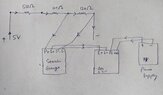
so i do not have 600 full ( i have 510+100) , the circuit given belowsophiecentaur said:That’s better. I could believe that. So you learned a lesson about ‘garbage in garbage out’.
So build it and draw a proper diagram of your circuit. See what Arduino does now.
This is a very common situation for a home experimenter. The 'wanted' 1V is not critical so whatever you get will be 'near enough for Jazz' as long as you got your sums right.Micheal_Leo said:so i do not have 600 full ( i have 510+100) , the circuit given below
so the circuit is good ?sophiecentaur said:This is a very common situation for a home experimenter. The 'wanted' 1V is not critical so whatever you get will be 'near enough for Jazz' as long as you got your sums right.
I have no idea what that wiring picture is about. You have TWO power supplies??? Why don't you get used to drawing a proper conventional circuit diagram with straight lines, right angled bends when needed - Just like the ones you can see everywhere else?Micheal_Leo said:so the circuit is good ?
yes i have two power supplies , one for AD620 and one for strain gauge ,sophiecentaur said:I have no idea what that wiring picture is about. You have TWO power supplies??? Why don't you get used to drawing a proper conventional circuit diagram with straight lines, right angled bends when needed - Just like the ones you can see everywhere else?
Remember what I told you about speaking English. So Speak proper circuit diagrams. Practice and look at the millions you can find on the net.
i have supplied 5v to both strain guage and AD620 , however while measuring output from AD620 , mV values fluctuates a lot , even the beam not bendBaluncore said:Why do you have 6 volt supply for AD620?
Can you not use 5 volts for AD620 and Bridge supply?
Maybe that is because you have not met the common mode input requirements of the AD620. At the bottom of page 3, of the AD620 data sheet, is shown the common mode input voltage range.Micheal_Leo said:i have supplied 5v to both strain guage and AD620 , however while measuring output from AD620 , mV values fluctuates a lot , ...
just did experiment that i remove AD620 and connect DMM with S+ and S+ of strain gauge , mv fluctuates a lot while beam not bendBaluncore said:Maybe that is because you have not met the common mode input requirements of the AD620. At the bottom of page 3, of the AD620 data sheet, is shown the common mode input voltage range.
I list the input design voltages in order, for a supply of +5 V.
The order of computation is 1, 2, 3, 4.
1. Vp = +5 V. Positive power supply.
2. Vp – 1.4 V = 3.6 V. Maximum AD620 CM input voltage.
4. Voltage at top of bridge = 3.35 V; ( 5.0 - 3.35 ) * 120Ω = 198 ohms.
3. Vin midpoint = ( 2.1 + 3.6 ) / 2 = 2.85 V = ideal S+ and S- voltages.
4. Voltage at bottom of bridge = 2.35 V; 2.35 * 120Ω = 282 ohms.
2. Vn + 2.1V = 2.1 V. Minimum AD620 CM input voltage.
1. Vn = 0 V. Negative power supply.
Check: 198Ω + 282Ω = 480Ω = 120Ω x 4 = 4 volts dropped external to the bridge.
So the resistors to use will be:
From Vp to top of bridge use = 100Ω + 100Ω = 200Ω.
From Vn to bottom of bridge use = 100Ω + 180Ω = 280Ω.
Then you have bad connections, or a crack in the strain gauge trace.Micheal_Leo said:just did experiment that i remove AD620 and connect DMM with S+ and S+ , mv fluctuates a lot
Or a noisy power supply.Baluncore said:Then you have bad connections, or a crack in the strain gauge trace.
i turn off power supply to guage and Ad620 , the DMM values jumping goes to -400 and moreTom.G said:Or a noisy power supply.
Or maybe you have a finger on a meter probe - or on a wire.
Or maybe you have long wires that pick up electrical noise from a close radio or TV transmitter - or from a fluorescent or LED light.
Please try it with the power supply turned Off but Everything else the same.
Cheers,
Tom
i have successfully tested DMM by paste one linear strain guage at beam, some assumptions has been made however the DMM is good, i am doubt for my strain gauge there is something wrong in my circuit.Tom.G said:Or a noisy power supply.
Or maybe you have a finger on a meter probe - or on a wire.
Or maybe you have long wires that pick up electrical noise from a close radio or TV transmitter - or from a fluorescent or LED light.
Please try it with the power supply turned Off but Everything else the same.
Cheers
Micheal_Leo said:i beleive this strain guage that i have posted not.getting any current or may be strain gauge below some cut connections , so confused
thank you very much going to try thisBaluncore said:Make four good wire connections to a strain gauge bridge.
Measure the resistance of the gauge with a DMM.
For a bridge made from four 120 Ω elements.
P+ to P-, and S+ to S- should measure a stable 120 Ω.
Any P, to any S, should measure a stable 90 Ω.
To detect broken elements, flex the bridge while measuring resistance. If you see 360 Ω, in place of 90 Ω, the element you are measuring is open circuit. If you see 240 Ω, in place of 120 Ω, there is a faulty element.