Understanding example in Wikipedia entry for open circuit voltage

  • Thread starter Thread starter zenterix
  • Start date Start date
  • Tags Tags
    Electromagnetism
AI Thread Summary
The discussion focuses on understanding the concept of open-circuit voltage, particularly in relation to a circuit involving a 5Ω resistor. The key point is that when the resistor is disconnected, no current flows through it or resistor B, leading to a potential drop across resistor C determined by the voltage source. Participants clarify that the absence of current through resistor B is due to it having no path for current flow, while the open-circuit voltage is derived from the voltage source across resistors A and C. There is also a distinction made between open-circuit and closed-circuit conditions, with the latter resulting in a different potential difference due to the presence of resistor B. Overall, the conversation emphasizes the mathematical relationships and physical principles governing open-circuit voltage.
zenterix
Messages
774
Reaction score
84
Homework Statement
I was trying to understand what an open-circuit voltage is so I looked it up on Wikipedia.
Relevant Equations
There is an example there that is the following.
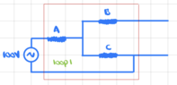
Consider the circuit (Wikipedia, Open Circuit Voltage)

1688773711669.png


If we want to find the open-circuit voltage across the 5##\Omega## resistor, first disconnect it from the circuit:

1688773748718.png

Find the equivalent resistance in loop 1 to find the current in loop 1. Use Ohm's law with that current to find the potential drop across the resistance C. Note that since no current is flowing through resistor B, there is no potential drop across it, so it does not affect the open-circuit voltage.

The open-circuit voltage is the potential drop across the resistance C, which is: ##\frac{C}{C+A}100V_{~}##

I am having a bit of difficulty understanding the steps and concepts here.

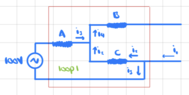
I redrew the circuit as follows

1688774102689.png

The red square is the same piece of the circuit with the dotted lines around it in the original diagram (not sure what this is for though).

It is not clear to me why there is no current through resistor B. This is my main question.

Assuming that this is true, then the current will be the same everywhere in loop 1 and resistors A and C are in series so

$$R_{eq} = R_A+R_C$$

and we obtain the current as

$$i=\frac{V}{R_{eq}}=\frac{V}{R_A+R_C}$$

We can find the potential drop through C from

$$V-R_Ai-R_Ci=0$$

$$R_Ci=V-R_Ai=V-\frac{R_AV}{R_A+R_C}=\frac{VR_C}{R_A+R_C}$$

which agrees with Wikipedia.
 

Attachments

  • 1688774326510.png
    1688774326510.png
    3.5 KB · Views: 112
  • 1688774465279.png
    1688774465279.png
    6.2 KB · Views: 96
Physics news on Phys.org
zenterix said:
Homework Statement: I was trying to understand what an open-circuit voltage is so I looked it up on Wikipedia.
Relevant Equations: There is an example there that is the following.

which agrees with Wikipedia, except for the sign.
That's because you made an algebraic error. The second equation does not follow from the first.
$$V-R_Ai-R_Ci=0$$ $$R_Ci=R_Ai-V$$
 
A little after writing out my original question I realized the following. "Open circuit" means that the terminals between which we are calculating potential are disconnected from anything. Any potential difference in this circuit is coming from the AC voltage source.

Current doesn't flow through B because it has nowhere to go after that (though this seems intuitively ok, is there a more technical explanation in terms of the math involved?). My guess is that there is no electric field in that section and therefore no potential difference.

Anyways, if no current flows through B, then it will flow through the closed circuit which is loop 1.

When we close the circuit (with the 5##\Omega##) resistor, then we have a potential difference. Now, I believe this potential difference will be different from the open circuit potential difference because of the presence of resistor B. Is this correct?
 
You got the general idea. However, your guess
zenterix said:
that there is no electric field in that section and therefore no potential difference.
is not a good one. There is an electric field between the open points and a potential difference ##V_L## between them. If you place a charged particle in that region, it will experience a force and move from a region of high potential energy to a region of low potential energy. If you connect the two points with a resistor, there will be a current. The situation (minus resistors A, B and C) is similar to any of the electrical outlets that you have at home.
 
Thread 'Struggling to make relation between elastic force and height'
Hello guys this is what I tried so far. I used the UTS to calculate the force it needs when the rope tears. My idea was to make a relationship/ function that would give me the force depending on height. Yeah i couldnt find a way to solve it. I also thought about how I could use hooks law (how it was given to me in my script) with the thought of instead of having two part of a rope id have one singular rope from the middle to the top where I could find the difference in height. But the...
Thread 'Voltmeter readings for this circuit with switches'
TL;DR Summary: I would like to know the voltmeter readings on the two resistors separately in the picture in the following cases , When one of the keys is closed When both of them are opened (Knowing that the battery has negligible internal resistance) My thoughts for the first case , one of them must be 12 volt while the other is 0 The second case we'll I think both voltmeter readings should be 12 volt since they are both parallel to the battery and they involve the key within what the...
Back
Top