What is the correct method for counting poles in a 3-phase induction motor?

  • Thread starter Thread starter BlackMelon
  • Start date Start date
  • Tags Tags
    Induction motor
AI Thread Summary
The discussion centers on determining the correct number of poles in a 3-phase induction motor, with one participant initially claiming it has 2 poles based on the number of slots and coils. However, upon analyzing the current waveforms and applying the right-hand rule, it was concluded that the motor actually has 6 poles. The conversation highlights that the number of poles should not be multiplied by the number of phases, as the motor operates based on the combined effect of all phases. Ultimately, the correct distribution of windings was identified as crucial for accurate pole counting. The final consensus emphasizes that 6 adjacent phase zones form one pole in the air gap.
BlackMelon
Messages
43
Reaction score
7
(I have modified the picture a little bit for clarity)

Hi there!

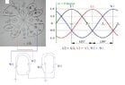
I had a chat with my colleague. He believes that the 3-phase induction motor on the picture below has 2-poles.
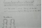
There are 12 slots. Each phase contain 2 coils. I have showed how the coils are connected for the phase W at the bottom.
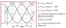
The waveform belongs to current of each phase. For notations, when the current is entering the slot W1 (crossed symbol in the hand drawing), the same current leaves the slot W2 (dotted symbol in the hand drawing).

So from the waveform, I take a sample of current flows when wt = 0 degree, where w is angular frequency (U1 = 0, W1 = positive, V1 = negative). Using the right hand rule, I founded that there are 6 poles.

I would like to know whether me or my colleague made any mistakes?Melon.

1694708297878.jpeg
 

Attachments

  • 1694703027030.jpeg
    1694703027030.jpeg
    41.1 KB · Views: 129
Last edited:
Engineering news on Phys.org
If you made a mistake, then it is probably observational, and we have been presented with the same data.

The ultimate test needs to be: does the unloaded motor run just below synchronous speed, or just below half twice synchronous speed.
 
Last edited:
Aren't number of poles is usually defined per phase?
 
Averagesupernova said:
Aren't number of poles is usually defined per phase?
Well, I understand your point. You bring the phase W like I drew and then examine its number of poles (4 poles).
However, when you input the 3 phase currents into the motor, the number of poles will not be 4x3. Rather, it will still be 4, considering the directions of all the currents in the stator.
Baluncore said:
If you made a mistake, then it is probably observational, and we have been presented with the same data.

The ultimate test needs to be: does the unloaded motor run just below synchronous speed, or just below half twice synchronous speed.
Thank you for the advice. :) :)
 
Guys, I got the answer for the question I asked. The distribution of windings' positions are incorrect. (The way I analyzed the number of poles was correct and showed abnormality). Rather, the distribution should be done as the picture below.
According to the right and rule (The thumb is the magnetic field. The rest of the fingers are the current). Please not that 6 adjacent phase zones form 1 pole in the air gap.
For example at 30 degree electrical angle, U, -V, W and -U, V, -W form a south pole.
1695272824009.jpeg


1695271093009.jpeg

1695271170161.jpeg
 

Attachments

  • 1695271081822.jpeg
    1695271081822.jpeg
    37.6 KB · Views: 121
  • 1695271104429.jpeg
    1695271104429.jpeg
    52 KB · Views: 105
Last edited:
Hi all I have some confusion about piezoelectrical sensors combination. If i have three acoustic piezoelectrical sensors (with same receive sensitivity in dB ref V/1uPa) placed at specific distance, these sensors receive acoustic signal from a sound source placed at far field distance (Plane Wave) and from broadside. I receive output of these sensors through individual preamplifiers, add them through hardware like summer circuit adder or in software after digitization and in this way got an...
I have recently moved into a new (rather ancient) house and had a few trips of my Residual Current breaker. I dug out my old Socket tester which tell me the three pins are correct. But then the Red warning light tells me my socket(s) fail the loop test. I never had this before but my last house had an overhead supply with no Earth from the company. The tester said "get this checked" and the man said the (high but not ridiculous) earth resistance was acceptable. I stuck a new copper earth...
I am not an electrical engineering student, but a lowly apprentice electrician. I learn both on the job and also take classes for my apprenticeship. I recently wired my first transformer and I understand that the neutral and ground are bonded together in the transformer or in the service. What I don't understand is, if the neutral is a current carrying conductor, which is then bonded to the ground conductor, why does current only flow back to its source and not on the ground path...
Back
Top