Tygra
- 55
- 8
- TL;DR
- Why am I getting incorrect signs
Hi there,
I was wondering if someone might know why I am getting incorrect signs for my structure that I am working on using the Direct Stiffness Method? I am following the procedure that I was taught when I was at University and I can't completely remember everything. I am designing a seven-storey structure that looks like this:

The magnitude of the forces I am getting is accurate, but the signs are incorrect.
Here are the bending moment on the structure:

You might not be able to see, but for the columns, you get a positive bending moment at the bottom of each storey and a negative bending moment at the top of the storey - this pattern is the same for each storey.
In my code I am getting positive bending moments at the top and the bottom, but like I said the magnitude is quite accurate.
Rather than post the entirity of my code, lets focus on a single column.
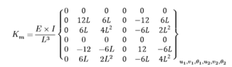
The local stiffness matrix for a column has the form:

And I set up the transformation matrix as follows:
To compute the global stiffness matrix you use the equation:

This will give you the global stiffness matrix! You can then proceed to find the displacements and rotations. Then you can find the internal forces on the structure.
I guess the thing to look at is the transformation matrix. Does it seem correct to you. The local stiffness matrix is definitely correct. I know you guys might not be Structural Engineers, but I am hoping some of you have experience with the Stiffness Method.
Many thanks in advance!
I was wondering if someone might know why I am getting incorrect signs for my structure that I am working on using the Direct Stiffness Method? I am following the procedure that I was taught when I was at University and I can't completely remember everything. I am designing a seven-storey structure that looks like this:
The magnitude of the forces I am getting is accurate, but the signs are incorrect.
Here are the bending moment on the structure:
You might not be able to see, but for the columns, you get a positive bending moment at the bottom of each storey and a negative bending moment at the top of the storey - this pattern is the same for each storey.
In my code I am getting positive bending moments at the top and the bottom, but like I said the magnitude is quite accurate.
Rather than post the entirity of my code, lets focus on a single column.
The local stiffness matrix for a column has the form:
And I set up the transformation matrix as follows:
Code:
T =

  6x6 table

              U1    V1    theta1    U2    V2    theta2
              __    __    ______    __    __    ______

    U1         0    1       0        0    0       0
    V1        -1    0       0        0    0       0
    theta1     0    0       1        0    0       0
    U2         0    0       0        0    1       0
    V2         0    0       0       -1    0       0
    theta2     0    0       0        0    0       1
To compute the global stiffness matrix you use the equation:
This will give you the global stiffness matrix! You can then proceed to find the displacements and rotations. Then you can find the internal forces on the structure.
I guess the thing to look at is the transformation matrix. Does it seem correct to you. The local stiffness matrix is definitely correct. I know you guys might not be Structural Engineers, but I am hoping some of you have experience with the Stiffness Method.
Many thanks in advance!