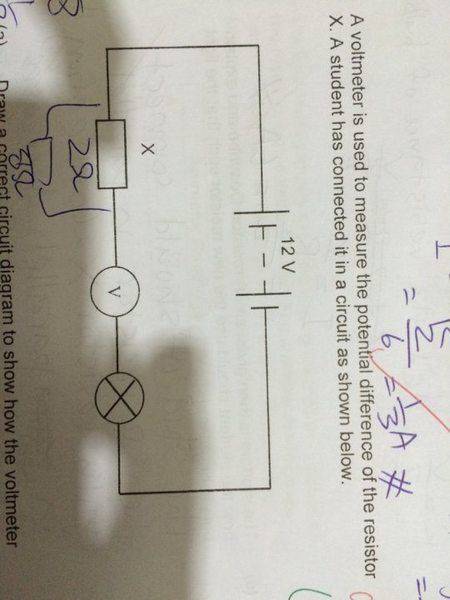
Why is current 12V÷2Ω instead of 12V÷(bulb resistance + 2Ω) in series?

  • Level: High School 
  • Thread starter Thread starter Lim Y K
  • Start date Start date
  • Tags Tags
    Current Series
Join the discussion
Registration is free. Start your own thread to ask a follow-up.
6 replies · 2K views
Lim Y K
Messages
26
Reaction score
0
Take this question as an example
ImageUploadedByPhysics Forums1440066974.082733.jpg

They asked for the current flowing through the bulb and the answer is 6A
I know that it's 12V divided by 2 ohms(2 ohm is the resistance of resistor X) , but why? I thought the current is supposed to be 12V divided by the resistance of bulb and resistor X(total resistance of resistors) since its arranged in series?
 
Physics news on Phys.org
As stated, the voltage across the resistor X is measured at 12 V, so the other parts of the circuit shouldn't matter.
 
Yes, current would be 12/(rtotal), where rtotal is the sum of the series resistances.

I'm not able to agree or disagree with you on the correctness of the textbook's answer, because you haven't disclosed the exact wording of the question. The figure you selected to use as an example is not a particularly good choice---because it examplifies a fundamental wiring "mistake".
 
  • Like
Likes   Reactions: CWatters and davenn
olivermsun said:
As stated, the voltage across the resistor X is measured at 12 V, so the other parts of the circuit shouldn't matter.

for a idea circuit, yes you could say that. But if it was a real world circuit, that is no longer true. The light globe will have significant resistance
which will change as it heats up

NascentOxygen said:
The figure you selected to use as an example is not a particularly good choice---because it examplifies a fundamental wiring "mistake".

indeed

@Lim Y K, can you recognise the problem ?Dave
 
davenn said:
for a idea circuit, yes you could say that. But if it was a real world circuit, that is no longer true. The light globe will have significant resistance
which will change as it heats up
I realize that is the case for a real incandescent lightbulb, but since the heated filament resistance, wasn't given in the problem, I'm assuming that the student isn't expected to incorporate that information in the solution.
 
maybe but they need to be informed that it isn't like that in the real world and you didn't give that clarification :smile:

the poor guy is already getting confused enough with incorrectly drawn circuits ...
 
olivermsun said:
As stated, the voltage across the resistor X is measured at 12 V, so the other parts of the circuit shouldn't matter.
This is not the case in the figure I'm seeing.