Wind Load Calculator: Gable Roof Envelope Procedure

4 replies · 11K views · last reply
medeek
Messages
46
Reaction score
6
I've recently started working on a wind load calculator.

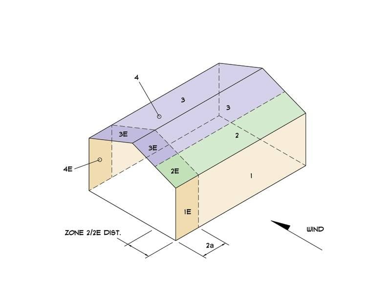
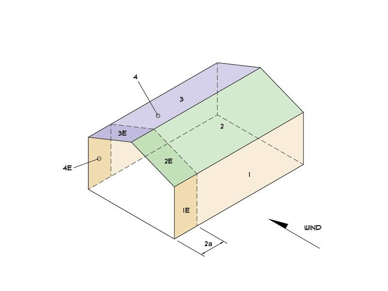
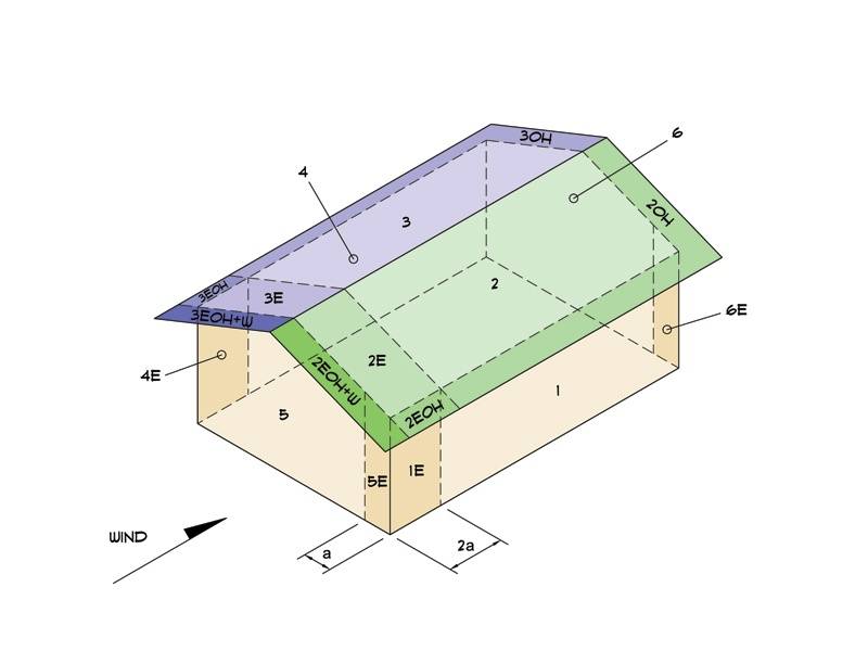
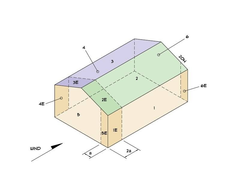
Notice the complexity when overhangs are added to the roof. These load diagrams show the Envelope Procedure for a Gable Roof:

Load Case A:
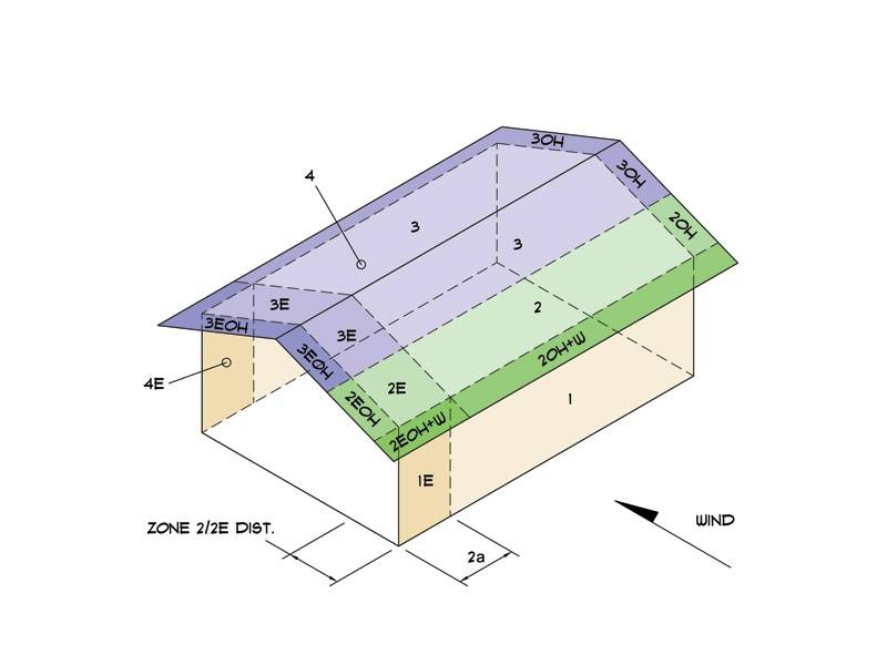
Wind load zone diagram of a gable roof building with overhangs, showing zones 1, 1E, 2, 2E, 2OH, 2OH+W, 2EOH, 2EOH+W, 3, 3E, 3OH, 3EOH, 4 and 4E, a wind arrow, and the label Zone 2/2E dist. with dimension 2a.


Isometric diagram of a gable roof building with wind zones labelled 1, 1E, 2, 2E, 2EOH, 2EOH+W, 2OH, 2OH+W, 3, 3E, 3EOH, 3OH, 4 and 4E, and a dimension 2a at the base corner.


Isometric diagram of a gable-roofed building showing ASCE 7 envelope procedure zones labelled 1, 1E, 2, 2E, 3, 3E, 4 and 4E, with dimension labels 2a and ZONE 2/2E DIST., and a wind arrow.


Isometric diagram of a gable-roof building with zones labelled 1, 1E, 2, 2E, 3, 3E, 4 and 4E, a wind arrow, and dimension 2a along the base.


Load Case B:

Isometric diagram of a gable-roof building with overhangs under the Envelope Procedure, showing numbered wall and roof zones (1 to 6, with E and OH variants), dimensions a and 2a, and a wind arrow at lower left.


Isometric diagram of a gable-roofed building with zones labelled 1, 1E, 2, 2E, 2H, 3, 3E, 4, 4E, 5, 5E and 6, 6E; wind arrow at lower left, and dimensions a and 2a along the base.


If torsional load cases are required then another Load Case A and B are required for the torsional load case.

Give the gable roof option a whirl, all of the other options are not programmed yet and I may never add them pending further research as to how well I can extrapolate the Envelope Procedure to these configurations.

If there are no overhangs set the overhang values to zero, I will need to add in a footnote about that later just to clarify.

Not a finished product yet, not by a long shot. The current Todo list includes the following:

To Do List:

1) Calculate min. lateral load with roof forces neglected and min. pressures of 8 psf and 16 psf on roof and walls respectively. (psf)
2) Calculate max. uplift and max. horizontal reactions of trusses or rafters assuming 24" o/c and 16" o/c for design of hurricane ties (lbs).
3) Calculate base wind shear in transverse and longitudinal direction (lbs).
4) Calculate shear wall reactions (lbs) and unit shear (plf) assuming only external shear walls (4 walls).
5) Calculate roof diaphragm distributed load (plf) assuming one story building with external shear walls only.
6) Include C & C wind loads for component design.
7) Include Directional Procedure as a comparison to Envelope Procedure or setup separate calculator for this method.
8 ) Complete PDF report output.

http://design.medeek.com/resources/wind/wind_calculator.pl
 
Interesting to note that for a gable roof only the wind forces on the walls contribute any lateral forces to the roof diaphragm and then to the shear walls for the longitudinal direction (wind parallel to ridge).

The breakdown of the forces would then be:

Transverse:

Diagram of wind load distribution on a gable roof building: horizontal bars for leeward roof, windward roof and walls with formulas like (3EOH)(OHG)(tanθ) =, (2EOH+W)(OHG)(tanθ) =, (4E)(hw/2) =, above a beam with supports R1 and R2 and dimensions 2a, L - 2a, L and OHG.


Longitudinal:

Diagram of a gable roof under wind load: triangular roof with gable ends, wall panels below, and a simply supported beam beneath with supports R_A and R_B, with labelled moment-arm and load expressions in the roof and wall areas.


One could argue that there is a certain amount of wind force on the edge of overhangs but I'm thinking its insignificant.
 
Shearwall reactions are now complete, assuming of course that only the exterior walls are acting as shear walls. This assumption is pretty useless for building with dimensions exceeding a certain limit since they will probably involve steel moment frames or multiple internal shear walls. I'm wondering if it might be useful to add some sort of advanced option which let's one specify an internal shearwall spacing or even a internal shearwall layout. The programming would get pretty complex.

I also added the ability to calculate truss/rafter uplift and horizontal load. Not entirely sure how useful this is either but I've personally ran into it enough times so I thought it might be of some benefit. The funny thing is after writing the code and creating the image for this section (3) I happened to look at a truss manufacturer's output for a garage I was designing a while back. I quickly noticed that the horizontal reactions and uplift were listed on the document, so if you've already taken your design to get the trusses quoted you probably don't need this information calculated. Just out of curiosity I used the same parameters as the truss manufacturer used for their wind loads and after adjusting for the TC and BC dead loads both my horizontal reactions and uplift were within 0.5 lbs of their values. Nothing like a third party check nailing it so perfectly, that is why I love this stuff.

Diagram of a gable roof truss with load annotations: uplift load on top, horizontal windward and leeward loads at the sides, and reactions U1 and U2 at the supports, with dimensions D, w/2 and w.
 
This is my best guess at the pressure distributions for Dutch Gable, Half Hip and Flat Roof types using the Envelope Procedure:

Isometric diagram of a hip-type roof on a rectangular building with wind-pressure zones labelled 1, 1E, 2, 2E, 2EOH, 2EOH+W, 2OH+W, 3, 3E, 3EOH, 3OH and 4, 4E, with a wind arrow and a dimension labelled 2a.


Isometric diagram of a hip-style roof on a building with wind arrow, showing zoned wind load regions labelled 1, 1E, 2, 2E, 2EOH, 2OH, 2OH+W, 3, 3E, 3OH, 4 and 4E, plus the zone 2/2E distance and 2a dimension.


Isometric diagram of a rectangular building under wind load showing zones labelled 1, 1E, 2, 2E, 3, 3E, 4 and 4E on the walls and roof, with WP, LP and a Zone 2/2E dist. dimension marked, and a wind arrow.
 
Compare the pressure profiles for a hip with the gable roof(Load Case A):

Isometric diagram of a hip roof on a rectangular building showing numbered wind pressure zones 1, 1E, 2, 2E, 2EOH, 2OH+W, 3, 3E, 3EOH, 3OH and 4, 4E, with a wind arrow and dimensions labelled Zone 2/2E dist. and 2a.


Isometric diagram of a gable roof building showing wind pressure zones on roof and walls, labeled 1, 1E, 2, 2E, 2OH, 2OH+W, 2EOH, 2EOH+W, 3, 3E, 3EOH, 3OH, 4, 4E, with wind arrow and dimensions Zone 2/2E dist. and 2a.


The calculations to resolve the pressures on the roof surfaces into lateral forces for the hip roof is going to get a little more involved.
 
Attachments
  • Isometric diagram of a hip roof on a rectangular building showing wind pressure zones labeled 1, 1E, 2, 2E, 2EOH, 2OH+W, 3, 3E, 3EOH, 3OH, 4 and 4E, with the wind arrow pointing toward the lower right and dimension labels Zone 2/2E dist. and 2a.
    HP_A1A_800.jpg
    27.8 KB · Views: 1,309