Help with wheels, stopping forces and possibly Simpack

In summary: We need to assume a friction force between the wheel and the wood block. We can do that by adding the weight of the person on the train and the weight of the wood block. Now we have two forces: the weight of the person on the train and the weight of the wood block. The weight of the person on the train is greater than the weight of the wood block, so the chock does not slide. The next question is how steep the slope needs to be to prevent the chock from sliding. The slope of the chock needs to be steep enough so that the vertical component of the wheel force is greater than the friction force. In summary,
  • #1
Woldennis
10
4
Hi all,

I am new to the forum and hoping for some help please.

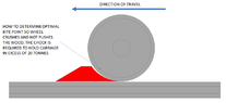
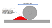
I work in the rail industry and we use chock blocks to stop trains or carriages rolling. I would like to know about the technical side of how and why the chock stops the wheel from moving. Obviously it wedges the wheel to stop movement but i am keen to learn what is the optimal point in terms of angle of slope required depending on the wheel size etc. From testing them i know that too step of a slope is detrimental as the wheel pushes and not crushes the wood so the block slides along but surely there must be some calculation that determines the optimal point to wedge a wheel etc.

I have seen simpack software that looks like it could provide some insight in helping with testing and providing data etc but have no idea where to begin.

So what i am kind of asking is there anyone that can provide some insight and help teach me some basics of how to calculate stuff like this or if simpack is even the correct thing i should be looking at.

Thanks in advance
 
Engineering news on Phys.org
  • #2
:welcome:
I like your question. I did a search and found this paper.

https://flightsafety.org/amb/amb_jan-feb93.pdf

It says:
Extensive testing by the U.S. Air Force and several major manufacturers has confirmed some basic design standards. The shape of the chock is extremely important. An approximate 45-degree chocking angle to the contact face with the tire is ideal. A more gradual slope may result in “pinching” the chock between the tire and the ramp if the airplane is loaded with additional fuel and/or passengers while chocked. A contact face steeper than 45 degrees may reduce the contact friction with the ramp and allow the chock to skid if the brakes are released.
 
Last edited by a moderator:
  • #3
Welcome to PF. :smile:

Woldennis said:
So what i am kind of asking is there anyone that can provide some insight and help teach me some basics of how to calculate stuff like this or if simpack is even the correct thing i should be looking at.
Are the rails and wheel materials generally the same (steel)? So each would have the same coefficient of friction to the wood chock blocks? Or could there potentially be different coefficients of friction at the two contact areas?

It seems like an initial calculation could be fairly straightforward, but then the effect of the pinching of the wedge between the two contact points will require some approximations (we'll need to guess how big the contact patches are, which will depend a bit on the deformation of the wood wedge blocks...
 
  • Like
Likes Lnewqban
  • #4
Thanks both for replies.

In terms of materials, the track is steel as are the wheel sets. The chock is steamed beech. The wheel sets range from 720 to 840mm.

I’ve added 2 very crude drawings.

The wood tends deform on the inside (flange ) side of the wheel
 

Attachments

  • 04F3C3A5-7E06-44FE-A424-339DCF2D558D.png
    04F3C3A5-7E06-44FE-A424-339DCF2D558D.png
    13.5 KB · Views: 80
  • 1B8C53AA-BF46-42DC-94B3-2A7CC52D6B06.png
    1B8C53AA-BF46-42DC-94B3-2A7CC52D6B06.png
    12.1 KB · Views: 95
  • #5
Woldennis said:
From testing them i know that too step of a slope is detrimental as the wheel pushes and not crushes the wood so the block slides along but surely there must be some calculation that determines the optimal point to wedge a wheel etc.
You are correct, there is a way to calculate chocks. But it can get complicated, so we start with the simplest case. There is no need for a sophisticated software package because hand methods work. We start with a free body diagram (FBD). Search that term. The Wikipedia article is a good place to start.

Below is a FBD of a wheel and chock. The wheel has a force against the chock. That force is perpendicular to the face of the chock. The ground has a force against the chock. That force has two components, a vertical force perpendicular to the bottom of the chock, and a friction force parallel to the bottom of the chock. The wheel force can be separated into two components. One component is vertical, the other component is horizontal.

Since the chock is not moving (important for this analysis), all vertical forces sum to zero, and all horizontal forces sum to zero. The vertical component of the wheel force is equal to the vertical force between the chock and the ground (or rail). The horizontal component of the wheel force is equal to the horizontal component of the force between the chock and the rail. If the ratio of the horizontal component to the vertical component of the chock/rail force is greater than the friction coefficient between the the chock and the rail, the chock slides. If less, it does not slide.

Chock.jpg

The above simplified analysis assumes zero friction between the wheel and the chock. The next step is to add a friction force between the wheel and the chock. That force is equal to the wheel force multiplied by the friction coefficient between wheel and chock, and is parallel to the face of the chock. Then sum horizontal and vertical components as above to find if the chock slides.
 
  • Informative
Likes berkeman
  • #6
Woldennis said:
The chock is steamed beech.
Interesting. I'm a bit curious as to why that material is chosen for this application. Is the reason historical, or does it have some properties that are superior to other alternatives (like hard rubber)?
 
  • #7
The beech is historically used and has proved well over time. Oak tends to split too much
 
  • #8
jrmichler said:
You are correct, there is a way to calculate chocks. But it can get complicated, so we start with the simplest case. There is no need for a sophisticated software package because hand methods work. We start with a free body diagram (FBD). Search that term. The Wikipedia article is a good place to start.

Below is a FBD of a wheel and chock. The wheel has a force against the chock. That force is perpendicular to the face of the chock. The ground has a force against the chock. That force has two components, a vertical force perpendicular to the bottom of the chock, and a friction force parallel to the bottom of the chock. The wheel force can be separated into two components. One component is vertical, the other component is horizontal.

Since the chock is not moving (important for this analysis), all vertical forces sum to zero, and all horizontal forces sum to zero. The vertical component of the wheel force is equal to the vertical force between the chock and the ground (or rail). The horizontal component of the wheel force is equal to the horizontal component of the force between the chock and the rail. If the ratio of the horizontal component to the vertical component of the chock/rail force is greater than the friction coefficient between the the chock and the rail, the chock slides. If less, it does not slide.

View attachment 318805
The above simplified analysis assumes zero friction between the wheel and the chock. The next step is to add a friction force between the wheel and the chock. That force is equal to the wheel force multiplied by the friction coefficient between wheel and chock, and is parallel to the face of the chock. Then sum horizontal and vertical components as above to find if the chock slides.
Thanks for this, will sit down later and go through it all. I take it you have a lot of experience in this field.
 
  • #9
Right I've read through it and I think I kind of get it but where do I start with actual calculations in real world?
 
  • #10
Diagram with actual dimensions. *Assume a round number for wheel force. Just get started and keep at it until you get to the end. This is one of those problems where trying to fully understand it before starting will suck you into a black hole. So just get started.

Since sliding is calculated from a ratio, the exact numbers do not make a difference. Start with 10 lbs, 100 lbs, or 1000 lbs makes no difference in the final answer.

And yes, I do have a lot of experience at solving these types of problems. So when I suggest just getting started, that's experience talking.

* Real physicists want you to do it all using letters and algebra, but people like me find it easier to use numbers.
 
  • #11
So is this enough info to get started with?
 

Attachments

  • wheel test 2.png
    wheel test 2.png
    5.4 KB · Views: 94
  • #13
Woldennis said:
So is this enough info to get started with?
Sorry that should 840 dia nor radius
 
  • #15
Same principle I think but wheel chocks seem to sit higher up the wheel. They should be 25% of the wheel to be effective.

Rail chocks are principally there to stop a wheel rolling, mainly for maintenance.

However there are major issues in being left in place and driven over causing a derailment.
 
  • Like
Likes Lnewqban
  • #16
  • #17
Woldennis said:
So is this enough info to get started with?
I would have thought that the 2 different radii were for the main wheel and the flange, no? If so, the chock should be contacting the main wheel and not the flange?

Anyway, it seems like the two extremes would be a rectangular block and a very low angle wedge. The rectangular block would not work because none of the wheel pressure is transferred to the block and the block just slides down the rail with a little friction based on its own weight as the wheel pushes it along. In the low-angle wedge case, the wheel can roll up and over the wedge, so that won't restrain the train motion well at all.

In between there will be an angle (or maybe more than one) where the weight transfer from the wheel to the wedge/chock is optimum for the friction forces between the wheel and the chock, and the chock and the rail, so that the most sideways force can be resisted before something slips. It certainly seems like a curved wheel-shaped chock would work best -- is that common? It looks from the pictures like some chocks are straight and some are curved? Also, the train has to be heavy as all heck -- do these chocks ever crumple and fail?
 
  • #18
Lnewqban said:
It seems that the rail chocks clamp onto the rail.
I'm not sure about that. It looks more like the vertical flange is to help locate the chock more accurately, not for a clamp. If there were some sort of lateral clamping mechanism, that would change the OP's question significantly...
 
  • Like
Likes Lnewqban
  • #19
Lnewqban said:
It seems that the rail chocks clamp onto the rail.
Note that the brake of the unit should be applied to prevent any movement, especially when loaded and parked on less than perfectly flat terrain.
The chocks are never meant to stop a moving unit.
Thats correct in some aspects, some clamp to rail other don't. The ones I use in my industry are wooden, the wedge stops the unit rolling once brakes are released.

You can motor over them if left in but it is dangerous
berkeman said:
I would have thought that the 2 different radii were for the main wheel and the flange, no? If so, the chock should be contacting the main wheel and not the flange?

Anyway, it seems like the two extremes would be a rectangular block and a very low angle wedge. The rectangular block would not work because none of the wheel pressure is transferred to the block and the block just slides down the rail with a little friction based on its own weight as the wheel pushes it along. In the low-angle wedge case, the wheel can roll up and over the wedge, so that won't restrain the train motion well at all.

In between there will be an angle (or maybe more than one) where the weight transfer from the wheel to the wedge/chock is optimum for the friction forces between the wheel and the chock, and the chock and the rail, so that the most sideways force can be resisted before something slips. It certainly seems like a curved wheel-shaped chock would work best -- is that common? It looks from the pictures like some chocks are straight and some are curved? Also, the train has to be heavy as all heck -- do these chocks ever crumple and fail
Thanks for the replies.

Maybe i need to explain a bit more how our ones are used as it might answer a few questions.

The flange doesnt come into contact with the chock at all. I will post a pic of a close up.

We use both a straight wedge and a curved variant in the industry in UK. For passenger trains each carriage is approx 20 tonnes so heavy enough.

The principle use is when a train stops in a depot for maintenance, the 2 scotches are placed on a wheelset or pair of wheels (depending on company), this is to prevent the train rolling when brakes are released to work on the train. It takes very little momentum to move a train and as such doesnt take a lot to stop it.

I have seen 3 car units move with a pry bar and few people pushing, because of this you can stop a unit moving with a small wedge.

The problem we find is they get left in place and driven over and this causes derailments although i believe we have limited this by designing a new style block. Even after being driven over the wood isnt destroyed, it is damaged but could be used over and over again. Possibly the grain of the beech as previously mentioned.

The main issue is to stop train rolling.
Second issue is it has to be driven over and not pushed along. This is more dangerous as when the speed builds up the block will snag and derail at speed, very dangerous
.

Problems i have encountered are when train moves if accidentally left in.
Curved, curve can be in contact across the length of the face of the chock. From testing this then tends to push the block along if curve is wrong for the wheel.

Also with curved the length of face causes issues as the wheel rolls up i then almost mates perfectly with the block so the contact area is the whole face which i think just pushes the block again. So again the curve needs to be shallower than the

And before anyone says just take it out lol, in this industry it just happens. Wrong i know but until we fix the mentality and processes, which will take years, we have to try to limit the problems.
 
  • Like
Likes Lnewqban
  • #20
Here are a few pics
20211103_122922.jpg
DJI_20221122_141609_25.jpg
 
  • Like
Likes berkeman and Lnewqban
  • #21
berkeman said:
Interesting. What is the difference between "Rail Chocks" and "Wheel Chocks"?
Rails are crowned, streets are much flatter. The wheels on the train cars are slightly concave. I assume this is to keep the wheels centered on the rails so the wheel flanges are not doing the work of keeping the train on the track; that would be sliding friction due to the different diameters of the wheel and flange, in addition to requiring rather tight tolerances.

If you have ever stood close to a train going around a curve, you may have heard the squeaking of the wheel flanges against the rails. Not something that you would want all along a cross-country trip.
 
  • Informative
  • Like
Likes berkeman and Lnewqban
  • #22
Tom.G said:
The wheels on the train cars are slightly concave. I assume this is to keep the wheels centered on the rails
Not a pure conical section.
The wheels are fixed to the axle, so when moving both have to settle at the same radius on the conical section to avoid any sliding.

A used wheel can wear into a concave, where I can imagine if two points have the same radius, some hunting can occur as the wheel can't decide which point to use to rotate at the same angular velocity as its mate.
 
  • #23
Woldennis said:
And before anyone says just take it out lol, in this industry it just happens. Wrong i know but until we fix the mentality and processes, which will take years, we have to try to limit the problems.
Airplanes have a checklist to complete before taking off.
Perhaps one can apply some of that expertise, before letting a car move down the track.
 
  • #24
Woldennis said:
Also with curved the length of face causes issues as the wheel rolls up i then almost mates perfectly with the block so the contact area is the whole face which i think just pushes the block again. So again the curve needs to be shallower than the
Shouldn't really matter what the curve profile is.
What would matter is the height of the block.
Too high and the horizontal force from the wheel overwhelms the frictional force of the block on the track, and the block slides.
 
  • #25
Woldennis said:
The problem we find is they get left in place and driven over and this causes derailments

The main issue is to stop train rolling.
Second issue is it has to be driven over and not pushed along. This is more dangerous as when the speed builds up the block will snag and derail at speed, very dangerous
.And before anyone says just take it out lol, in this industry it just happens. Wrong i know but until we fix the mentality and processes, which will take years, we have to try to limit the problems.
That reminds me of the fuse principle, although that would imply a mechanism.

If not much force is needed to move a wagon, not much force is needed to keep it from moving.
A simple block of wood will can't do much more than being pushed forward or rolled over.

I wonder if the block could be made such that it flattens when the engine is increasing the force on it inducing the wheel to roll over it.
At the same time, increase friction of bottom surface against rail, and then make it jump out of the track, so the following wheel does not catch it.

 
Last edited:

1. What is the purpose of using Simpack in wheel design?

Simpack is a software tool used for multi-body simulation, which is particularly useful in designing and analyzing complex mechanical systems like wheels. It allows engineers to simulate the motion and forces acting on each individual component of the wheel, providing a better understanding of its performance.

2. How do wheels generate stopping forces?

Stopping forces are generated by the friction between the wheel and the surface it is in contact with. When the brakes are applied, the brake pads press against the wheel, creating a friction force that slows down the rotation of the wheel and ultimately brings the vehicle to a stop.

3. How does the design of a wheel affect its stopping performance?

The design of a wheel can have a significant impact on its stopping performance. Factors like the size and material of the wheel, the brake system used, and the weight of the vehicle can all affect the amount of friction and stopping force generated. A well-designed wheel with efficient brakes can provide better stopping performance.

4. Can Simpack be used to optimize wheel design for better stopping performance?

Yes, Simpack can be used to simulate different wheel designs and analyze their performance in terms of stopping forces. By tweaking various parameters like wheel size, material, and brake system, engineers can use Simpack to optimize the design and improve stopping performance.

5. How do engineers determine the optimal wheel size for a vehicle?

The optimal wheel size for a vehicle is determined by considering various factors like the weight and size of the vehicle, the intended use, and the desired performance. Simpack can be used to simulate different wheel sizes and analyze their impact on the vehicle's performance, helping engineers determine the optimal size for a particular vehicle.

Similar threads

Replies
22
Views
2K
Replies
15
Views
1K
Replies
4
Views
9K
Replies
9
Views
2K
Replies
3
Views
1K
  • General Engineering
2
Replies
47
Views
7K
  • Engineering and Comp Sci Homework Help
Replies
18
Views
1K
  • Engineering and Comp Sci Homework Help
Replies
23
Views
2K
  • Introductory Physics Homework Help
2
Replies
44
Views
5K
  • General Engineering
Replies
10
Views
3K
Back
Top