Pipsqueakalchemist
- 141
- 20
- TL;DR
- Simulink modelling of rotary inverted pendulum for LQR (Linear-Quadratic Regulator) implementation on hardware
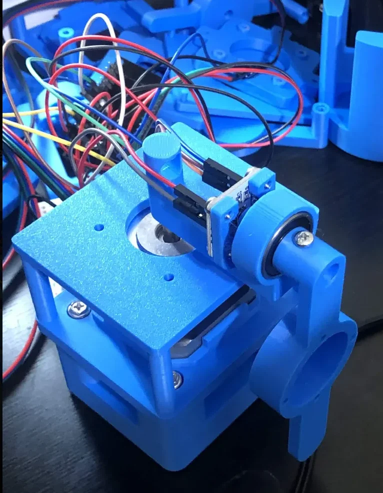
I'm trying to work on a rotary inverted pendulum project. I have an image of it below where most of the stuff is 3D printed.
My electronics is NEMA17 stepper, ESP32 devkit v1, TMC2208 v1.2, and AS5600 encoder for pendulum sensing. I was planning to use the accelstepper library to keep track of step count for rotor position sensing.
I derived the dynamics and developed my LQR controller to spit out rotor acceleration, u = q1ddot(rad/s^2), so my state space was x = [q1 q2 q1dot q2dot] where q1/q1dot are rotor angle/velocity and q2/q2dot are pendulum angle/velocity.
So since my control was rotor acceleration then xdot = [q1dot q2dot u f(q1,q2,q1dot,q2dot,u)] where f = q2ddot is function I found from rearranging the dynamics equation I derived.

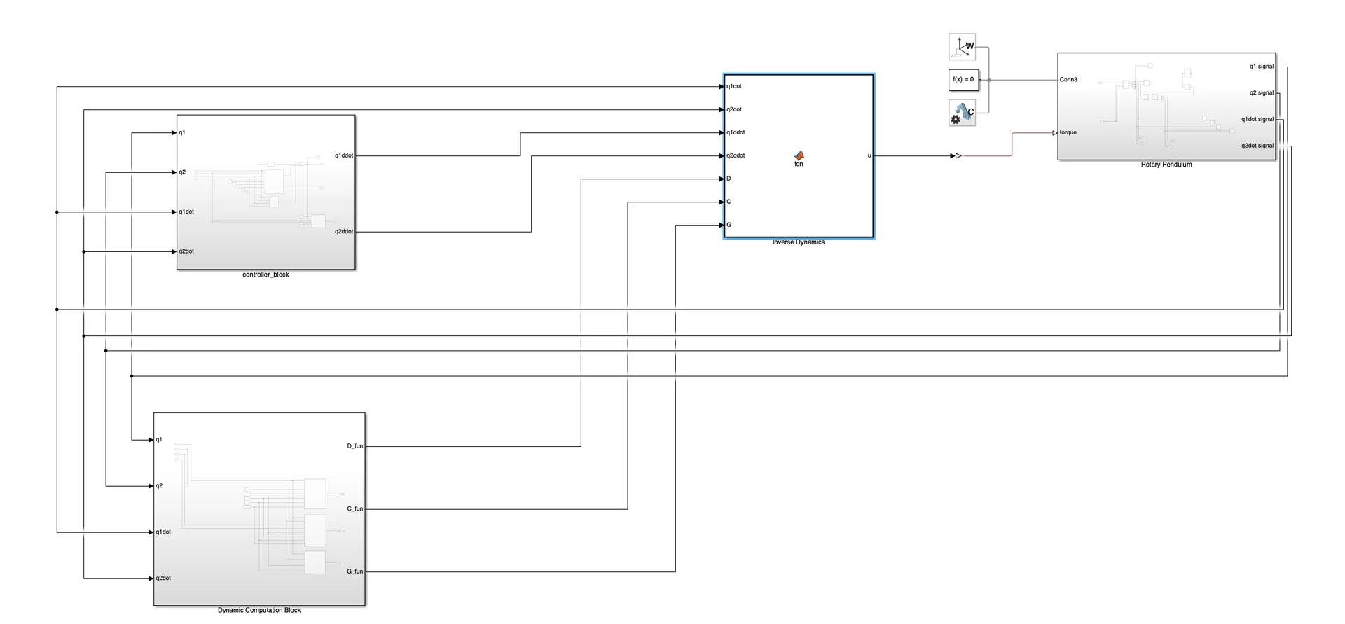
Then I linearized xdot using Jacobian matrix about equilibrium point xbar = [0 0 0 0] to obtain my A and B matrix to obtain gains for LQR. I created a Simulink model that essentially feeds in the full states into the controller block which contains the LQR controller + energy based swing up controller. Then obtain rotor acceleration u = q1ddot then I used inverse dynamics to convert it to torque and apply it to the rotary plant. The issue is that this simulink model doesn't represent my hardware that well.
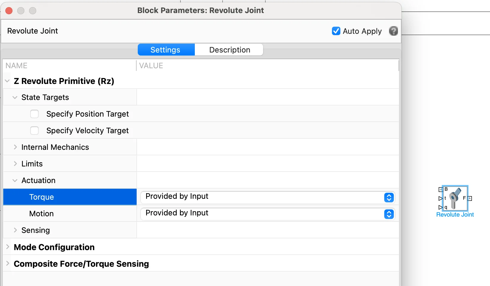
In order to improve my simulink model I'm going to import my CAD model. I wanted to ask what good experiment should I run on my rotary hardware and log it on Serial monitor and send that data to simulink to improve my model. Also I'm not 100% sure how I would model the nema17 stepper. If it was DC motor I could use the DC motor equations. In Simulink I can only input into the revolute joint either torque or angle, so I could either perform inverse dynamics like before and get torque, or I could double integrate the acceleration and input position. I'm not sure which model is more realistic way to model nema17. And if I did do the double integration method, I think it would be
speed = prev_speed + accel x period
angle = prev_angle + speed x period
I would appreciate any help on this, I understand the theory and can get things working in simulation but I'm having issues applying it to hardware, so I'd appreciate any advice from people who have. Thank you
My electronics is NEMA17 stepper, ESP32 devkit v1, TMC2208 v1.2, and AS5600 encoder for pendulum sensing. I was planning to use the accelstepper library to keep track of step count for rotor position sensing.
I derived the dynamics and developed my LQR controller to spit out rotor acceleration, u = q1ddot(rad/s^2), so my state space was x = [q1 q2 q1dot q2dot] where q1/q1dot are rotor angle/velocity and q2/q2dot are pendulum angle/velocity.
So since my control was rotor acceleration then xdot = [q1dot q2dot u f(q1,q2,q1dot,q2dot,u)] where f = q2ddot is function I found from rearranging the dynamics equation I derived.
Then I linearized xdot using Jacobian matrix about equilibrium point xbar = [0 0 0 0] to obtain my A and B matrix to obtain gains for LQR. I created a Simulink model that essentially feeds in the full states into the controller block which contains the LQR controller + energy based swing up controller. Then obtain rotor acceleration u = q1ddot then I used inverse dynamics to convert it to torque and apply it to the rotary plant. The issue is that this simulink model doesn't represent my hardware that well.
In order to improve my simulink model I'm going to import my CAD model. I wanted to ask what good experiment should I run on my rotary hardware and log it on Serial monitor and send that data to simulink to improve my model. Also I'm not 100% sure how I would model the nema17 stepper. If it was DC motor I could use the DC motor equations. In Simulink I can only input into the revolute joint either torque or angle, so I could either perform inverse dynamics like before and get torque, or I could double integrate the acceleration and input position. I'm not sure which model is more realistic way to model nema17. And if I did do the double integration method, I think it would be
speed = prev_speed + accel x period
angle = prev_angle + speed x period
I would appreciate any help on this, I understand the theory and can get things working in simulation but I'm having issues applying it to hardware, so I'd appreciate any advice from people who have. Thank you