Watching port impedance in the a field monitor values

  • Thread starter yefj
  • Start date
4 replies · 532 views · last reply
yefj
Messages
166
Reaction score
2
Hello ,I have a basic dipole antenna with 70 ohm port.
I put time domain H-field and E-field monitors.
does dividing the real values E/H on a cutting plane will give me 70 ohms traveling as the time goes by?
if the 70 ohm takes 1ns to travel from excitation to the ends what does it mean?
Thanks.
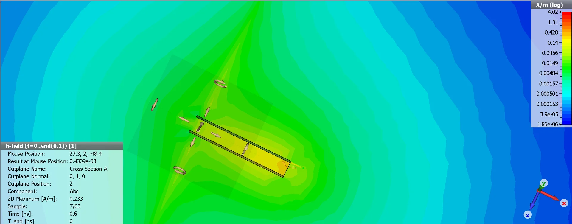
Simulation screenshot of the H-field magnitude (A/m, log colour scale from 1.86e-06 to 4.02) around a flat two-conductor structure, with a cross-section plane and arrow vectors; a panel lists cutplane and sample readings.
 
I mean in general, we have transient field solvers .
can i see the port impedance in the E/H of a transient field monitors.

I have a differential transmission line with port characterstic impedance of 100Ohm.
When I put field monitors on the line. The values if the E and H are real.
Can I see the port charateristic impedance in E/H traveling wave?
 
Last edited:
yefj said:
I have a differential transmission line with port characterstic impedance of 100Ohm.
Wowee. Do you have an unbalanced 50 Ohm coax feeding an ideal dipole antenna through a balun, or do you have a 100 Ohm balanced differential pair transmission line feeding something else?
 
Last edited:
yefj said:
if the 70 ohm takes 1ns to travel from excitation to the ends what does it mean?
A dipole can be modelled as a transmission line, λ/2 long, open at the ends. The impedance at the ends of the dipole are infinite, with zero current, so the dipole becomes a resonator.

How can you model a dipole in free space, on or near a transmission line in the same model.

If the dipole were modelled as two transmission lines above a ground plane on a PCB, then each open-ended line would need to be λ/4 long, and have an impedance of 35 Ω, so when the dipole is centre-fed, the two are in series, presenting an impedance of 70Ω to the differential feed. But you claim to have a 100 Ω differential feed, so there will be a mismatch at the 70Ω dipole centre.

70 ohms does not travel, it is the ratio of voltage to current in a circuit, or the electric field to magnetic field when propagating.
You have no length scale, dipole wavelength, or dielectric constant, so numbers are impossible. Maybe 1 ns is the time it takes an impulse to travel from the generator to the ends of the dipole, or is it the TDR return time of the reflected signal from the feed-point mismatch?