Engineering Using Kirchhoff's Laws to Solve a Circuit with Two Batteries

Click For Summary
SUMMARY

This discussion focuses on applying Kirchhoff's Laws to analyze a circuit with two batteries. The user calculated the current (I) and internal resistance (Ri) using the formulas I = P/U and U_a = U_q - R_i*I, arriving at values of 0.46 A and 0.43 Ohm respectively. The user faced challenges in calculating the total power (P) of the circuit, initially estimating it at 2.09 W. Through collaborative insights, they determined the load resistance (RL) to be 9.25 Ohm, which resolved their power calculation issue when plugged back into the formulas.

PREREQUISITES
  • Understanding of Kirchhoff's Laws
  • Familiarity with Ohm's Law
  • Basic circuit analysis techniques
  • Ability to perform calculations involving voltage, current, and resistance
NEXT STEPS
  • Study advanced applications of Kirchhoff's Laws in complex circuits
  • Learn about circuit simulation tools like LTspice or Multisim
  • Explore power calculation techniques in electrical circuits
  • Review video tutorials on systematic methods for applying Kirchhoff's Laws
USEFUL FOR

Electrical engineering students, circuit designers, and anyone looking to deepen their understanding of circuit analysis using Kirchhoff's Laws.

sylent33
Messages
39
Reaction score
5
Homework Statement
When a resistor R is connected, the terminal voltage of a battery is equal to
U = 4.3 V and the power in the resistor P = 2W. The battery is said to be ideal
Voltage source can be modeled with internal resistance.
a)What is the internal resistance Ri of the battery if its source voltage Uq =
4.5 V?
b)At which load resistance would the terminal voltage be U = 4 V?
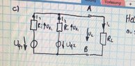
cYou connect a second, identical battery in parallel. How does the power change from point a)? Draw the circuit and label all sizes.
Relevant Equations
P = UI
Okay so This is what I've tried;

a) A formula I've found in the lecture notes;

$$ U_a = U_q - R_i*I $$ To get I used the ## I = \frac{P}{U} ## formula I get I to be 0,46 A.Now put back in formula for and rearange to get Ri should be

$$ \frac{Ua-Uq}{I} = Ri $$ and the solution should be 0,43 Ohm.

b) I used the same formula as in the first one but here I simply rearanged to get I

$$ I = \frac{Uq-Ua}{Ri} $$ I = 1,16; and now ## R = \frac{U}{I} ## = 3,44 Ohm.

Now I think these two should be fine,I've checked the work with a few friends and it matches.

c) Here I am having problems.I've drawn the picture and I've tried a few things but I am not really having much succsses with it; This is my picture;(attachment) Now P should be 2,09W but I don't see how.What I've tried is adding both currents since they both are going in the same knot(above I2) and I Kirchoffs Law.With that new current,I've tried finding P but the value is not correct.Any insights? Thanks
 

Attachments

  • IMG-20201029-WA0003.jpg
    IMG-20201029-WA0003.jpg
    67.5 KB · Views: 160
  • Like
Likes Delta2
Physics news on Phys.org
What is the total resistance of the circuit?
I = Uq / ( Ri + RL )
 
Baluncore said:
What is the total resistance of the circuit?
I = Uq / ( Ri + RL )
Ah okay that I kind of overlooked.I've tried it again;

Now looking at your formula I think that the values of Ri and RL are simply the ones I calculated; so after calculating I again it should be I = 1,11 A . Now I think this should be the current of the circuit.Now to get the power of the entire circuit; P = U * I ;

Now this doesn't give me the wanted 2,09 W. I've also tried calculating the resistance of the circuit by considering that Ri are in parallel to each other but that didnt help. Could it be that the I i calculated is not what I think that it is?
 
sylent33 said:
Now looking at your formula I think that the values of Ri and RL are simply the ones I calculated
Where did you calculate RL for a)?

Do you know how to use Kirchoff's laws, including a systematic method for getting the signs right?
 
I'll chip in...

For Part a) the current is ##\frac {2}{4.3}## A. Rounded to 2 sig. figs. this is 0.47A, not 0.46A
________________

For Part b) you may be required to round 3.44Ω to 3.4Ω if answers are required to 2 sig. figs.
__________________

For Part c), you haven’t shown your calculations but here are a couple of hints.

Hint 1: You must calculate the load resistance used in Part a).

Hint 2 (if you don’t want to use Kirchhoff’s laws): Two identical batteries, each with voltage source (emf) ##U_q## and internal resistance ##R_i## connected in parallel act as a single battery with voltage source (emf) ##U_q## and internal resistance ##\frac {R_i} {2}##.
 
So as I have seen just know I didnt realize that the RL in b and a was diffrent.My apologies. I did it just know and it should be RL = 9,25 Ohm.Now using the hint from Steve and this new RL I get the result I wanted (if we plug it into the formula I used earlier).But I am interested in the approach with Kirchoffs Law since we covered it in class and I think this is the way the exercise was susposed to be solved.I know both of them,but the systematic method for getting the signs right is kind of confusing.I am assuming you mean that if we sum up all of the voltages and the sign is negative than we just assumed the direction of the voltages wrong? So if I would to use the Kirchoffs Laws (which I would like to try it) I would need two loops and try to calculate the voltages out of that?
 
sylent33 said:
But I am interested in the approach with Kirchoffs Law since we covered it in class and I think this is the way the exercise was susposed to be solved.I know both of them,but the systematic method for getting the signs right is kind of confusing.I
There are variations on how Kirchhoff’s laws are used, but all are equivalent. Have you tried any YouTube videos? This one is OK (plenty of others available):
For your circuit in Post #1, for the 2 loops I would choose:
1) the right hand loop (containing ##U_{q2}, R_{i2}## and ##R_L##);
2) the outer (perimeter) loop (containing ##U_{q1}, R_{i1}## and ##R_L##)

Note ##U_{q1} = U_{q2}##. And ##R_{i1} = R_{i2}##, though you have labelled them both as ##R_i##.

Have a go. Post your equations if you want them checking.

Also note we often use lower case ‘r’ for internal resistance, so we could use symbols ##r_1## and ##r_2##. [Minor edit made.]
 

Similar threads

  • · Replies 2 ·
Replies
2
Views
2K
  • · Replies 8 ·
Replies
8
Views
2K
  • · Replies 3 ·
Replies
3
Views
2K
  • · Replies 10 ·
Replies
10
Views
2K
  • · Replies 2 ·
Replies
2
Views
1K
  • · Replies 15 ·
Replies
15
Views
2K
  • · Replies 11 ·
Replies
11
Views
3K
  • · Replies 27 ·
Replies
27
Views
4K
  • · Replies 3 ·
Replies
3
Views
2K
  • · Replies 4 ·
Replies
4
Views
2K