How Do I Draw This Shear and Moment Diagram?

  • Thread starter Thread starter pawer
  • Start date Start date
Join the discussion
Ask a follow-up here, or get your own question answered by working scientists, mathematicians and engineers — people, not an autocomplete.
Real named experts · corrections over time · the nuance an AI answer skips
12 replies · 3K views
pawer
Messages
6
Reaction score
1
Thread moved from the technical forums to the schoolwork forums
Hi everyone,

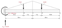
Can anyone tell me how do I draw the shear and moment diagram of below pic
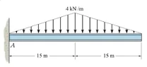
Shear_and_Moment.webp

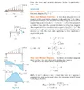
using the method like below pic?

Shear_and_Moment_example.webp

This is my attempt/work of the reacting forces:
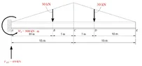
Reacting_Force.webp

Thank you very much for the help.
 
Physics news on Phys.org
I think since it's on equilibrium state, so the reaction forces can be easily found.
 
pawer said:
I think since it's on equilibrium state, so the reaction forces can be easily found.
Welcome!
But if the only point of anchorage of the beam to the ground is exerting 450 kN of vertical force to keep that equilibrium state, which vertical loads are inducing that reaction?
 
Lnewqban said:
Welcome!
But if the only point of anchorage of the beam to the ground is exerting 450 kN of vertical force to keep that equilibrium state, which vertical loads are inducing that reaction?

It was my mistake, sorry. It should be 60 kN.

Reacting_Force_Corrected.webp


Reacting_Force_Corrected.webp
 
Last edited by a moderator:
Reply
  • Like
Likes   Reactions: Lnewqban
How do I draw the Shear and Moment diagram of this problem?
 
Lnewqban said:
Have you done it before for simpler cases?

I can draw the shear and moment diagram like post #1.

The book I am reading about shear and moment diagram does not show example of what I'm asked.

At which point the x is located so that I can find the function of x of this problem?
 
pawer said:
At which point the x is located so that I can find the function of x of this problem?
There is no point at which x is located.
For each cross-section of the beam represented by any x distance from the point of anchorage to the wall along the beam, there are specific values of shear and moment loads.

Without doing any calculation, we know that the beam's cross-section that is resisting the maximum value of moment is located at the point of anchorage A, and that the end of the beam (cross-section E) will not be fighting any moment.

The intensity of the resisting moment will decrease squarely from A to E, but not following a single parabola because the pattern of the load distribution changes at point C.

The shear-moment combined loads that the cross-sections located between E and C are resisting could be analyzed as if that length of the beam were anchored to a wall located at C (this would not work for calculations of the beam's deflection).

The analysis of the shear-moment combined loads that the cross-sections located between A and C are resisting would need to consider the actual shear and moment loads that the section located at C is experiencing (as previously analyzed above).
 
This is my work. Can someone please tell me how do I find the one in red, question symbol?

Shear_and_Moment_(worked_example).webp