AN/APG-81 AESA radar antenna structure type

9 replies · 9K views · last reply
ryaamaak
Messages
16
Reaction score
11
This is the AN/APG-81 AESA Radar antenna by Northrop Grumman currently found in the F-35 (photo from wikipedia article).
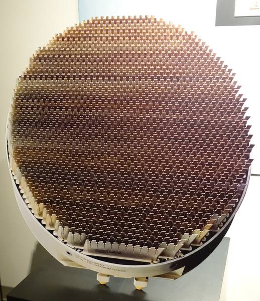
Circular AESA radar antenna face with a dense grid of many small, uniform radiating elements arranged in a regular pattern, mounted on a white circular housing.

It seems to have a very different structure than past AESA/PESA antennas. For example the APG-68 from the F-16 looks a lot like stacked, slotted wave guides to me.

So what is the name of the actual structural layout for the APG-81? One person I talked to suggested "honeycomb", but I couldn't find any reference to that antenna structure on google scholar. Better search terms would be appreciated. :)

Thanks!
 
Attachments
  • Circular AESA radar antenna face with a dense grid of many small, uniform radiating elements arranged in a regular pattern, mounted on a white circular housing.
    AN-APG-81_Antenna%2C_2005_-_National_Electronics_Museum_-_DSC00393.jpg
    73.1 KB · Views: 2,587
Last edited by a moderator:
  • Like
Likes   Reactions: davenn and berkeman
Paul Colby said:
but I was going to suggest a Vivaldi Slot Array.

good thought, except Vivaldi slots are usually tapered, on closer inspection, these slots are a uniform width

ryaamaak said:
...
It seems to have a very different structure than past AESA/PESA antennas. For example the APG-68 from the F-16 looks a lot like stacked, slotted wave guides to me...
Thanks!

Yes, that antenna definitely appears to be sets of slotted waveguides, a big giveaway is the offset of the slots along each guide
that is the norm. for slotted WG's

do you have a link to a larger pic of this antenna ?

youtube video from Northrop Grumman for the radar
other videos on the topic ...


Dave
 
Last edited:
  • Like
Likes   Reactions: ryaamaak
davenn said:
good thought, except Vivaldi slots are usually tapered, on closer inspection, these slots are a uniform width

The elements on the periphery may be parasitic elements. It's unclear to me if the metallization is seen. It may be on the side facing away in the picture. I'm happy for it not to be one though.
 
  • Like
Likes   Reactions: ryaamaak
Thanks everyone for the great input!

davenn said:
do you have a link to a larger pic of this antenna ?
Larger image may be found here. I wasn't able to embed it full size.
 
  • Like
Likes   Reactions: davenn
ryaamaak said:
Thanks everyone for the great input!

Larger image may be found here. I wasn't able to embed it full size.

yeah, I eventually found that in the wiki article when I was looking through those other links I posted :smile:

here's a closeup of a section

Close-up of a metal antenna array with rows of dark rectangular radiator elements mounted on a light grey housing; small printed text on the housing is too blurry to read.


This antenna is designed for around 10GHz plus/minus ~ 1GHz
I suspect each of those little bars at the top is a 1/4 or 1/2 wave at 10GHz (electrical 1/2 wave = ~ 1.4cm)
A tad difficult to tell the scale in that image
So basically you have masses of say 1/4 wave radiators and the rows of these radiators can be driven by the transmitter
in and out of phase to direct the beam as needed ... as shown in that 2nd or 3rd video I posted

a hint to how these radiators are grouped comes from a bit of that first video shortly in from the startDave
 
Attachments
  • Close-up of a metal antenna array with rows of dark rectangular radiator elements mounted on a light grey housing; small printed text on the housing is too blurry to read.
    10GHz radar phased array antenna.jpg
    44.9 KB · Views: 2,164
  • Like
Likes   Reactions: ryaamaak
On a similar theme

I have a phased array from a terrestrial microwave link antenna that I have had a difficult time to
understand the technology and how the heck it radiates/receives
I may post a pic when I get home fort your interest :smile:

Dave
 
  • Like
Likes   Reactions: ryaamaak
Ok I think I'm getting the gist of it. One article mentioned a diameter of approximately 0.7m for the APG-81, so an individual measurement of ~1.4cm seems plausible. Forgive me if this question has a self-evident answer, but would this radiator shape have a specific name or descriptive terms attached to it? (I'm thinking along the lines of how "dipole antenna" shaped elements are frequently used as passive radiators in a yagi-uda antenna.)

For comparison/contrast, the APG-77 from the F22 (below) has a similar structure to the APG-81, but the individual radiators are slightly different: not as tapered at the top, no deep slit between radiators, and confirmed use of GaAs.

Photo of a grey AESA radar antenna face showing a dense grid of small tapered radiator elements, mounted on a black base with Northrop Grumman and Raytheon logos.


Thanks!
 
Attachments
  • Photo of a grey AESA radar antenna face showing a dense grid of small tapered radiator elements, mounted on a black base with Northrop Grumman and Raytheon logos.
    lectronically_Scanned_Array%2C_Northrop_Grumman%2C_2001_-_National_Electronics_Museum_-_DSC00388.jpg
    55.2 KB · Views: 2,149
  • Like
Likes   Reactions: davenn
ryaamaak said:
Ok I think I'm getting the gist of it. One article mentioned a diameter of approximately 0.7m for the APG-81, so an individual measurement of ~1.4cm seems plausible. Forgive me if this question has a self-evident answer, but would this radiator shape have a specific name or descriptive terms attached to it? (I'm thinking along the lines of how "dipole antenna" shaped elements are frequently used as passive radiators in a yagi-uda antenna.)

For comparison/contrast, the APG-77 from the F22 (below) has a similar structure to the APG-81, but the individual radiators are slightly different: not as tapered at the top, no deep slit between radiators, and confirmed use of GaAs.

View attachment 225104

Thanks!
that's a cool variation

ryaamaak said:
For comparison/contrast, the APG-77 from the F22 (below) has a similar structure to the APG-81, but the individual radiators are slightly different: not as tapered at the top, no deep slit between radiators

not as deep as the other one but deeper than initially thought on first look see this ...

Close-up photo of a curved array of many small stepped metal radiating elements arranged in rows across a light grey panel, shown at an angle with a shadowed edge.


Close-up photo of stepped, serrated edges on pale grey panels, with small raised square features along each step, arranged in parallel strips against a curved surface.


they have the same stepped arrangement

I'm a radio tech at heart, this sort of high tech fascinates the hell out of me haha
 
Attachments
  • Close-up photo of a curved array of many small stepped metal radiating elements arranged in rows across a light grey panel, shown at an angle with a shadowed edge.
    10GHz radar phased array antenna2.jpg
    28.9 KB · Views: 1,803
  • Close-up photo of stepped, serrated edges on pale grey panels, with small raised square features along each step, arranged in parallel strips against a curved surface.
    upload_2018-5-4_14-15-15.png
    38 KB · Views: 1,742
  • Like
Likes   Reactions: ryaamaak
Now @Paul Colby earlier commented on Vivaldi antennas

Paul Colby said:
I can't see much detail from the picture but I was going to suggest a Vivaldi Slot Array. https://pdfs.semanticscholar.org/9fe2/60de5caeec3cdc36cbb2dbea50e7b5f2fc53.pdf

just stumbled on this pic of a real Vivaldi phased array for a radar
Note how the slot changes from wide to narrow aperture ... this gives it wide bandwidth

Close-up photo of a phased array radar antenna face at an exhibition, showing a dense grid of gold-coloured tapered flared elements with a grey metal housing at the right edge. Korean caption reads: 국산 AESA Radar 시제품, 청주에어쇼 2013-10-25 bemil.


going further

here's the block diag. of the feeding of the Vivaldi on the left and our other type on the right

Block diagram comparing two phased array feeds: on the left, four yellow tapered elements feed a beamformer labelled AMP and a combining tree; on the right, four yellow elements each feed an AMP, then D/A and A/D converters, all connected to a green block labelled FPGA/DSP/etc., separated by a red vertical line.
Dave
 
Attachments
  • Close-up photo of a phased array radar antenna face at an exhibition, showing a dense grid of gold-coloured tapered flared elements with a grey metal housing at the right edge. Korean caption reads: 국산 AESA Radar 시제품, 청주에어쇼 2013-10-25 bemil.
    10GHz radar phased array antenna3.jpg
    62.6 KB · Views: 3,314
  • Block diagram comparing two phased array feeds: on the left, four yellow tapered elements feed a beamformer labelled AMP and a combining tree; on the right, four yellow elements each feed an AMP, then D/A and A/D converters, all connected to a green block labelled FPGA/DSP/etc., separated by a red vertical line.
    AESA_1.png
    2.9 KB · Views: 2,103
  • Like
Likes   Reactions: ryaamaak and Paul Colby