An "x" from nowhere, mistake by textbook? (induced voltages)

AI Thread Summary
The discussion centers on the calculation of induced voltage and current in a physics problem involving magnetic fields. Participants identify a mistake in the textbook's approach to calculating the net force on a wire, specifically in how it applies the formula for force. The correct method involves using the magnetic fields at specific points along the wire, which the textbook fails to do accurately. One participant confirms their calculations yield a different result than the textbook, reinforcing the belief that the textbook's solution is incorrect. The conversation concludes with an appreciation for the clarification provided.
mymodded
Messages
29
Reaction score
7
Homework Statement
The long, straight wire in the figure has a current i= 1.00 A flowing in it. A square loop with 10.0-cm sides and a resistance of 0.0200 ##\Omega## is positioned 10.0 cm away from the wire. The loop is then moved in the positive x-direction with a speed v = 10.0 cm/s.

Calculate the direction and the magnitude of the net force acting on the loop at the instant it starts to move.
Relevant Equations
##\Delta V_{ind}=-\frac{d\Phi}{dt}##
##\Phi = \oint \vec{B} \cdot d\vec{A}##
##B_{long wire} = \frac{\mu_{0} i}{2\pi r}##
##F = ilB sin(\theta)##
1716985385886.png

this is the figure in the question.The question can be solved by first finding the induced voltage (and then the induced current), and then we can find the force on each side of the wire due to the magnetic field and subtract them from each other (since the force on the upper and lower sides are the same they cancel eachother so we only need to worry about the right and left side)

dA = 0.1 dr
##\Large \Delta V_{ind}=-\frac{d\Phi}{dt} = \frac{d}{dt}(\int_{0.1t+0.1}^{0.1t+0.2} \frac{\mu_{0} i}{2\pi r} 0.1 dr) = \frac{d}{dt}(\frac{0.1\mu_{0} i}{2\pi} (ln(0.1t+0.2) - ln(0.1t+0.1)) = \frac{0.1\mu_{0} i}{2\pi} . (\frac{0.1}{0.1+0.2} - \frac{0.1}{0.1t+0.1})##

then ##i_{ind}## is that divided by the resistance R.
then
##F_{net} = F_{right} - F_{left} = i_{ind} L B_{right} - i_{ind} L B_{left} ## where ##B= \frac{\mu_{0} i}{2\pi r}## and r is 0.1 for left and 0.2 for right and we substitute t = 0.
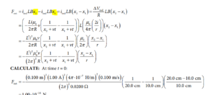
but the textbook solved the last part like this
1716986863866.png

which I believe is wrong, since when did F= ilbx? and when you calculate what they wrote you actually get 10^(-14)N not -16 . The answer that I got is 5*10^(-14) N so am I correct or is the textbook correct?
 

Attachments

  • 1716986810107.png
    1716986810107.png
    25.2 KB · Views: 93
Last edited:
Physics news on Phys.org
Yes, you are right. The textbook solution is wrong where it starts off with ##F_{net} = i_{ind}LBx_2 - i_{ind}LBx_1##.

As you noted, it should be ##F_{net} = i_{ind}LB(x_2) - i_{ind}LB(x_1)##,
where ##B(x_1)## is the magnetic field at ##x = x_1## and ##B(x_2)## is the magnetic field at ##x = x_2##.

I get an answer that's a factor of 10 different from yours. But I could be slipping up somewhere.
 
  • Like
Likes mymodded and MatinSAR
TSny said:
Yes, you are right. The textbook solution is wrong where it starts off with ##F_{net} = i_{ind}LBx_2 - i_{ind}LBx_1##.

As you noted, it should be ##F_{net} = i_{ind}LB(x_2) - i_{ind}LB(x_1)##,
where ##B(x_1)## is the magnetic field at ##x = x_1## and ##B(x_2)## is the magnetic field at ##x = x_2##.

I get an answer that's a factor of 10 different from yours. But I could be slipping up somewhere.
thanks a lot really appreciate it
 
Kindly see the attached pdf. My attempt to solve it, is in it. I'm wondering if my solution is right. My idea is this: At any point of time, the ball may be assumed to be at an incline which is at an angle of θ(kindly see both the pics in the pdf file). The value of θ will continuously change and so will the value of friction. I'm not able to figure out, why my solution is wrong, if it is wrong .
Thread 'Trying to understand the logic behind adding vectors with an angle between them'
My initial calculation was to subtract V1 from V2 to show that from the perspective of the second aircraft the first one is -300km/h. So i checked with ChatGPT and it said I cant just subtract them because I have an angle between them. So I dont understand the reasoning of it. Like why should a velocity be dependent on an angle? I was thinking about how it would look like if the planes where parallel to each other, and then how it look like if one is turning away and I dont see it. Since...
Thread 'Voltmeter readings for this circuit with switches'
TL;DR Summary: I would like to know the voltmeter readings on the two resistors separately in the picture in the following cases , When one of the keys is closed When both of them are opened (Knowing that the battery has negligible internal resistance) My thoughts for the first case , one of them must be 12 volt while the other is 0 The second case we'll I think both voltmeter readings should be 12 volt since they are both parallel to the battery and they involve the key within what the...
Back
Top