zimbabwe
- 33
- 0
For a lab we built the following circuit.
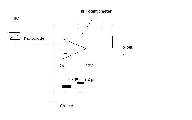
Our photo diode was receiving a blinking signal which our op amp made visible on a DVM.
I do not understand the purpose of the capacitors attached to the power rail.
So far I understand how negative feed back with the Rf resistor controls the amount of gain. Without negative feed back the op amp would produce near infinite gain. The maximum voltage that can come out of the op amp is + or - 12V but about the capacitors I am at a loss.
Any help would be appreciated.
Our photo diode was receiving a blinking signal which our op amp made visible on a DVM.
I do not understand the purpose of the capacitors attached to the power rail.
So far I understand how negative feed back with the Rf resistor controls the amount of gain. Without negative feed back the op amp would produce near infinite gain. The maximum voltage that can come out of the op amp is + or - 12V but about the capacitors I am at a loss.
Any help would be appreciated.
Last edited: