BJT amplifier - calculate resistances

  • Thread starter Thread starter etf
  • Start date Start date
  • Tags Tags
    Amplifier Bjt
Join the discussion
Ask a follow-up here, or get your own question answered by working scientists, mathematicians and engineers — people, not an autocomplete.
Real named experts · corrections over time · the nuance an AI answer skips
16 replies · 3K views
etf
Messages
179
Reaction score
2
Hi!
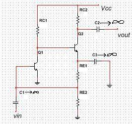
Here is my task:
Calculate RC1, RC2, RE2 for maximum undistorted symmetrical signal at output if DC collector currents are IC1=IC2=1mA. Calculate voltage gain Av.
Vcc=9V, RE1=1.8kΩ , VBE=0.7V, VCES=0.2V, VT=26mV, beta=100, VA→∞.
Solution: RE2=700Ω, RC1=5.724kΩ, RC2=3.141kΩ, Av=gm1*gm2*rpi2*RC1*RC2/(rpi2+RC1).

nik.JPG


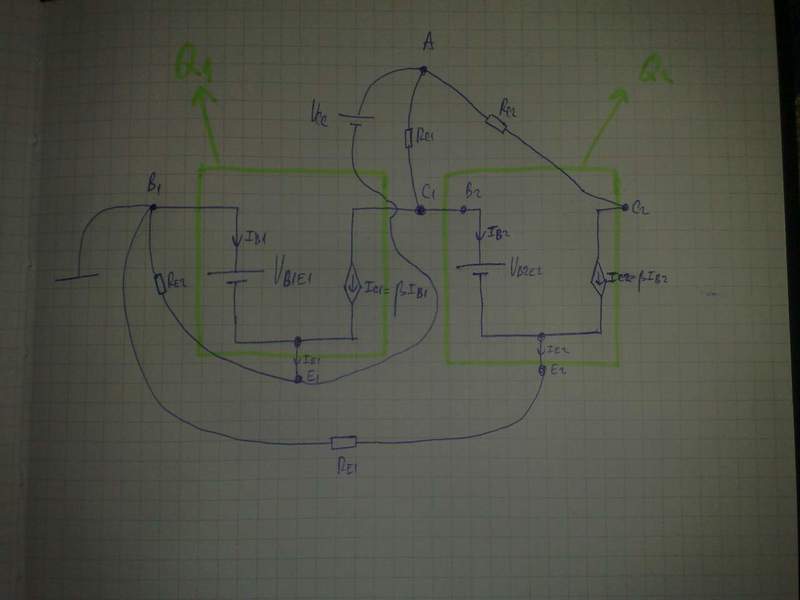
After assuming that BJT's operate in forward active mode and solving circuit bellow I got RE2=700Ω, RC1=5.782kΩ. Is it ok? How to find RC2? I have no problems calculating Av.
31052014894.jpg
 
Physics news on Phys.org
Re1 looks good
But you are slightly off the true Rc1 value.
What is the current that is flow Rc1 ? What is the voltage across Rc1?

As for the Rc2 maybe this will give you some hint
https://www.physicsforums.com/showthread.php?t=633117&highlight=swing
But for your circuit Vc is not equal to 4.5V. You must include DC emitter voltage and Vce(sat).
9V - (2.518 + 0.2) = 6.282V.
So to get maximum undistorted signal Vc2 must be equal to ??

P.S

What it is ??
https://www.physicsforums.com/attachment.php?attachmentid=70181&d=1401493487
 
Last edited:
Thanks, I will take a look on post... My second scheme is scheme for DC analysis, I just used models for BJT's in forward active mode (http://people.senecac.on.ca/john.kawenka/EDV255/images/bjt05.png ) instead of usual BJT symbol.
 
Last edited by a moderator:
Your DC model is incorrect. Try to draw it again.
 
etf said:
Whats wrong with model?
The model is ok. The overall diagram is wrong. Why T1 base is short to ground?
Why Vcc is connect is not connected to ground ?
 
E1 should be connected to ground, instead of B1. I don't know why I connected B1 to ground :)
 
Do you managed to find Vc2 voltage ?
 
I can't figure it out :(
 
What is the voltage at Q2 emitter ??
And notice that voltage at collector can swing from Ve2 + Vce(sat) up to Vcc.
So to get maximum undistorted symmetrical signal at collector we must chose Vc at the middle of this swing.
 
VE2=VC1E1-VB2E2=2.518V so voltage at collector (VC2) can swing from 2.518V+0.2V=2.718V up to Vcc=9V (6.282V swing). Now I should find Vc and after that RC2?
 
etf said:
VE2=VC1E1-VB2E2=2.518V so voltage at collector (VC2) can swing from 2.518V+0.2V=2.718V up to Vcc=9V (6.282V swing). Now I should find Vc and after that RC2?
Exactly, and you should pus Vc at the middle of the swing.
 
2*(vc2e2-0.2)=6.282 → vc2e2=3.341v.
Vc2e2+rc*ic2-rc1*ic1-vb2e2=0 → rc2=(rc1*ic1+vb2e2-vc2e2)/ic2
rc2=3141Ω
Thanks a lot!
 
The answer is good, but you over complicate this.
All you need to find Rc2 is to use a II Kirchhoff law for the output loop.

attachment.php?attachmentid=70196&stc=1&d=1401570058.png


Vcc = VRc2 + Vce2 + Ve2

Ve2 = Ie2*Re1 + Ic2*Re2 = 1.01mA*1.8kΩ + 1mA*700Ω = 2.518V

The swing

Vcc - (Ve2 + Vce(sat)) = 9V - (2.518V + 0.2V) = (9V - 2.718V) = 6.282V

From this VRc2 = Vce2 = 6.282V/2 = 3.141V

And

Rc2 = VRc2/Ic2 = 3.141/1mA = 3.141kΩ

And Rc1 = (Vcc - (Ve2 + Vbe2))/( Ic1 + Ib2 ) = 5.782V/(1mA + 10μA) = 5.724kΩ
 

Attachments

  • 31.PNG
    31.PNG
    2.2 KB · Views: 1,061
  • Like
Likes   Reactions: 1 person
I have another example.
Calculate resistances R1, R2, RC, RE for maximal symmetrical undistorted voltage on output, if total maximal collector current is Icmax=4mA. Vcc=10V, load resistance RL=10kΩ, β=100, VBE=0.7V, VCES=0.2V, VT=26mV, VA=100.

prvi.JPG


In DC analysis, I calculated VCE=VCC-(beta*RC/(RE*(beta+1))+1)*((VCC/R1-VBE/R1-VBE/R2)/(1/R1+1/R2+(1-beta/(beta+1))/RE)). For maximal swing Vce shoud be on middle of load line. I'm not sure I understand what total maximal collector current means :confused:
Here is solution:
RE=2*beta*(Vcc-VCES)/(Icmax*(1+beta))-(beta/(1+beta))*(RC*RL/(RC+RL)+RC)
R2=R1*(2*beta*VBE+(1+beta)*RE*Icmax)/(2*beta*(Vcc-VBE)-[R1+(1+beta)*RE]*Icmax)
 
Last edited:
OMG, how do you manage to derive the formula for RE and Vce ??
 
I'm also not sure what total maximal collector current is.
I see two options.
First:
Ic_max = Icq - quiescent DC current or maybe Ic_tot = Icq + Ic_ac ?

And to find components values we can use ohms law.
For example assume Veq = 1V and Icq = 1mA and from there we have
Re = 1V/1.01mA = 990Ω = 1K.
Rc = 4.5V/1mA = 4.4KΩ ≈ 4.3KΩ and voltage at base Vb = Veq + Vbe.
So you design voltage divider to get Vb at output. And the current that is flow through divider should be much larger than the Ib

http://eelinux.ee.usm.maine.edu/cou....BJT Amps. for Undistorted VoltageSwing-X.pdf