Calculating Input/Output Impedance w/ Parallel Resistors

In summary, the principle of superposition states that the current of a circuit can be calculated by using the AC voltage source and the DC voltage source respectively, and then adding the two currents to obtain the total current.
  • #1
ntetlow
21
2
Hello,
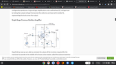
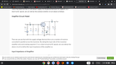
attached are two screenshots showing a common emitter and the same with source voltage removes to find the input impedance.
How is it that resistors R1 and RC can be placed in parallel to work out the input and output impedances?
Examples i have seen only show straightforward instances of parallel resistances.
If possible can someone also knock up a spice simulation where I can see for myself the proof. t
 

Attachments

  • Screenshot 2022-11-19 16.59.58.png
    Screenshot 2022-11-19 16.59.58.png
    28.3 KB · Views: 83
  • Screenshot 2022-11-19 16.59.38.png
    Screenshot 2022-11-19 16.59.38.png
    27.5 KB · Views: 69
Engineering news on Phys.org
  • #2
ntetlow said:
How is it that resistors R1 and RC can be placed in parallel to work out the input and output impedances?
Sorry, I don't understand. R1 and Rc are not in parallel. Can you show us you equivalent circuit for the impedance calculations?

ntetlow said:
If possible can someone also knock up a spice simulation where I can see for myself the proof.
Um... Sure it possible. Is it possible for you to do that yourself? I like LTSpice, myself, it's both free and good.

BTW, simulation is not a tool for "proofs". They often lie even when you think you've entered the data correctly. That's like proving something in a Math class with a hand calculator.
 
  • #3
I mean that R1 is in parallel to R2 and RC is in parallel to RE whereas before R1 was in series with R2 and RC was in series with RE.
 
  • Skeptical
Likes davenn
  • #4
ntetlow said:
I mean that R1 is in parallel to R2 and RC is in parallel to RE whereas before R1 was in series with R2 and RC was in series with RE.
Because the power supply is defined to have zero impedance and a constant voltage. For any signal except DC, it can be replace with a short circuit.

Even in DC analysis, the input and output impedances are defined by the change in voltage and current, i.e. ## Z_{in} = \frac{dV_{in}}{dI_{in}}##. So since the power supply voltage is held constant, you get the same answer for any value. That allows you to set it to zero.
 
  • #5
ntetlow said:
before R1 was in series with R2 and RC was in series with RE.
Nope. There's a transistor in there, which has 3 terminals. Components aren't in series if there is any path that allows an electron to go around one of them.
 
  • Like
Likes davenn
  • #6
ntetlow said:
How is it that resistors R1 and R2 can be placed in parallel to work out the input and output impedances?
This is a conceptual problem. Please see the picture below. How to calculate the AC current ##~I_s~##, isn't it obvious that ##R1## and ##R2## should be connected in parallel ?

20221123_200811.jpg

According to the principle of superposition, the current of the circuit can be calculated by using the AC voltage source and the DC voltage source respectively, and then adding the two currents to obtain the total current, but you only need to care about the AC current for calculating the AC impedance in this example.
 
Last edited:
  • Skeptical
Likes davenn
  • #7
alan123hk said:
isn't it obvious...
Not when you're learning this stuff.
 
  • Like
  • Informative
Likes davenn and Tom.G
  • #8
ntetlow said:
I mean that R1 is in parallel to R2 and RC is in parallel to RE whereas before R1 was in series with R2 and RC was in series with RE.

no they are not, for the reasons that DaveE stated
 

1. What is input/output impedance?

Input/output impedance refers to the measure of resistance that an electronic circuit presents to the flow of signal. It is typically expressed in ohms and can affect the performance and stability of a circuit.

2. How do you calculate input/output impedance with parallel resistors?

To calculate the input/output impedance with parallel resistors, you can use the formula: Z = 1 / ((1/R1) + (1/R2) + (1/R3) + ... + (1/Rn)). This means that you take the reciprocal of each resistor value, add them together, and then take the reciprocal of the sum to get the total impedance.

3. What is the purpose of using parallel resistors?

Parallel resistors are used to reduce the overall impedance of a circuit. This can be beneficial in certain applications where a lower impedance is desired, such as in audio systems or power supplies.

4. Can the input/output impedance with parallel resistors be lower than the individual resistors?

Yes, the total impedance with parallel resistors can be lower than the individual resistors. This is because the total resistance is calculated by adding the reciprocals of the individual resistors, which results in a smaller value.

5. How does the number of parallel resistors affect the input/output impedance?

The more parallel resistors there are in a circuit, the lower the overall impedance will be. This is because the total resistance is calculated by adding the reciprocals of the individual resistors, so adding more resistors will result in a smaller value.

Similar threads

Replies
3
Views
1K
  • Electrical Engineering
Replies
6
Views
1K
Replies
14
Views
2K
  • Electrical Engineering
2
Replies
38
Views
3K
Replies
8
Views
1K
Replies
19
Views
3K
Replies
8
Views
761
  • Engineering and Comp Sci Homework Help
Replies
1
Views
2K
Replies
15
Views
2K
  • Electrical Engineering
Replies
15
Views
1K
Back
Top