Calculating Input/Output Impedance w/ Parallel Resistors

Join the discussion
Ask a follow-up here, or get your own question answered by working scientists, mathematicians and engineers — people, not an autocomplete.
Real named experts · corrections over time · the nuance an AI answer skips
7 replies · 2K views
ntetlow
Messages
21
Reaction score
2
Hello,
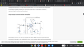
attached are two screenshots showing a common emitter and the same with source voltage removes to find the input impedance.
How is it that resistors R1 and RC can be placed in parallel to work out the input and output impedances?
Examples i have seen only show straightforward instances of parallel resistances.
If possible can someone also knock up a spice simulation where I can see for myself the proof. t
 

Attachments

  • Screenshot 2022-11-19 16.59.58.png
    Screenshot 2022-11-19 16.59.58.png
    28.3 KB · Views: 203
  • Screenshot 2022-11-19 16.59.38.png
    Screenshot 2022-11-19 16.59.38.png
    27.5 KB · Views: 186
Engineering news on Phys.org
ntetlow said:
How is it that resistors R1 and RC can be placed in parallel to work out the input and output impedances?
Sorry, I don't understand. R1 and Rc are not in parallel. Can you show us you equivalent circuit for the impedance calculations?

ntetlow said:
If possible can someone also knock up a spice simulation where I can see for myself the proof.
Um... Sure it possible. Is it possible for you to do that yourself? I like LTSpice, myself, it's both free and good.

BTW, simulation is not a tool for "proofs". They often lie even when you think you've entered the data correctly. That's like proving something in a Math class with a hand calculator.
 
I mean that R1 is in parallel to R2 and RC is in parallel to RE whereas before R1 was in series with R2 and RC was in series with RE.
 
Reply
  • Skeptical
Likes   Reactions: davenn
ntetlow said:
I mean that R1 is in parallel to R2 and RC is in parallel to RE whereas before R1 was in series with R2 and RC was in series with RE.
Because the power supply is defined to have zero impedance and a constant voltage. For any signal except DC, it can be replace with a short circuit.

Even in DC analysis, the input and output impedances are defined by the change in voltage and current, i.e. ## Z_{in} = \frac{dV_{in}}{dI_{in}}##. So since the power supply voltage is held constant, you get the same answer for any value. That allows you to set it to zero.
 
ntetlow said:
before R1 was in series with R2 and RC was in series with RE.
Nope. There's a transistor in there, which has 3 terminals. Components aren't in series if there is any path that allows an electron to go around one of them.
 
Reply
  • Like
Likes   Reactions: davenn
ntetlow said:
How is it that resistors R1 and R2 can be placed in parallel to work out the input and output impedances?
This is a conceptual problem. Please see the picture below. How to calculate the AC current ##~I_s~##, isn't it obvious that ##R1## and ##R2## should be connected in parallel ?

20221123_200811.jpg

According to the principle of superposition, the current of the circuit can be calculated by using the AC voltage source and the DC voltage source respectively, and then adding the two currents to obtain the total current, but you only need to care about the AC current for calculating the AC impedance in this example.
 
Last edited:
Reply
  • Skeptical
Likes   Reactions: davenn
alan123hk said:
isn't it obvious...
Not when you're learning this stuff.
 
Reply
  • Like
  • Informative
Likes   Reactions: davenn and Tom.G
ntetlow said:
I mean that R1 is in parallel to R2 and RC is in parallel to RE whereas before R1 was in series with R2 and RC was in series with RE.

no they are not, for the reasons that DaveE stated