Glenn Emmers
- 5
- 0
Dear all,
I'm currently working on an open core PCB rogowski coil and came up with the following design:
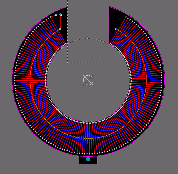

I concluded that the asymmetry wouldn't be a problem if the coil is centered precisely around the conductor and cause it's mainly supposed to operate around 50 Hz. Is this a good assumption?
The coil has 152 windings with the following approximated properties:
- Mutual inductance (M) = 40nH
- Resistance = 10.141 Ω
- Inductance = 8.019 μH
- Capacitance = 40.7nF
I'm supposed to measure currents up to 100A under normal conditions (higher in extraordinary cases)
For a HOKA, the integrator is replaced by a low pass filter and a gain is added afterwards. (Here is link with a bit of explanation).
So I have a couple of questions:
I thought the sensitivity of the Rogowski was also determined by the integration constant, with the sensitivity being: M/τ. But since I won't have an integrator, how will I be able to determine the sensitivity?
Also what is the best way to determine the parameters of this low pass filter and amplifier?
Can I put 2 rogowski coils in parallel to have less relative noise disturbance?
What Hall-sensors would be useful in this application?
I thank you in advance,
Glenn
I'm currently working on an open core PCB rogowski coil and came up with the following design:
I concluded that the asymmetry wouldn't be a problem if the coil is centered precisely around the conductor and cause it's mainly supposed to operate around 50 Hz. Is this a good assumption?
The coil has 152 windings with the following approximated properties:
- Mutual inductance (M) = 40nH
- Resistance = 10.141 Ω
- Inductance = 8.019 μH
- Capacitance = 40.7nF
I'm supposed to measure currents up to 100A under normal conditions (higher in extraordinary cases)
For a HOKA, the integrator is replaced by a low pass filter and a gain is added afterwards. (Here is link with a bit of explanation).
So I have a couple of questions:
I thought the sensitivity of the Rogowski was also determined by the integration constant, with the sensitivity being: M/τ. But since I won't have an integrator, how will I be able to determine the sensitivity?
Also what is the best way to determine the parameters of this low pass filter and amplifier?
Can I put 2 rogowski coils in parallel to have less relative noise disturbance?
What Hall-sensors would be useful in this application?
I thank you in advance,
Glenn
