Complex circuit and its resistance

AI Thread Summary
The voltage between points P and Q in the circuit is confirmed to be 1.5 V. The discussion revolves around determining the total resistance and understanding the configuration of resistors A, B, C, and D, particularly whether they are in series or parallel. It is clarified that resistors B and C are parallel, while C and D are not in series due to the presence of junctions affecting current flow. Participants emphasize the importance of redrawing the circuit for clarity and applying Kirchhoff's laws to analyze the circuit effectively. Ultimately, a clearer understanding of the circuit's configuration leads to the calculation of total resistance as approximately 28.29 Ohms.
Pouyan
Messages
103
Reaction score
8
Homework Statement
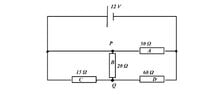
In the circuit shown below, I will determine the voltage between points P and Q. The answer is given but my problem is that I can not find the total resistance in the circuit.
Relevant Equations
V=R*I
PQ.jpg
The true answer is : The voltage between P and Q is 1.5 V.

I got stuck finding the total resistance. My question is:
Is B parallel to both A and C?
Is C parallel to D ?
I tried many ways to find the total R but failed!
My first attempt:
I say the system ABD is in serie with C:

$$\frac{1}{R_{A}} +\frac{1}{R_{B}} + \frac{1}{R_{C}} $$
and $$R_{ABD}=11.54\Omega $$

together with Rc :
$$R_{C}+R_{ABD}=26.54\Omega $$

$$I_{total}=\frac{12}{26.54}\textit{A}=0.45A$$

In this case when Rc is in seire with RABD, then the current is the same in both systems and the voltage at Rc = 15*0.45V=6.75V!
The voltage in the ABC is (12-6.75)V = 5.25 V.
The current IA is then at RA = $$\frac{5.25}{50} A$$
But it's not correct! since I know that VPQ=1.5 V!

How can I get the total R ?
 

Attachments

  • PQ.jpg
    PQ.jpg
    11.4 KB · Views: 133
  • 1622712613534.png
    1622712613534.png
    87 bytes · Views: 145
Physics news on Phys.org
Pouyan said:
I say the system ABD is in serie with C
This is incorrect as there is a wire from within the ABD system bypassing C entirely.

Are you familiar with Kirchhoff's circuit laws? If so you should apply them.
 
  • Like
Likes Pouyan
Pouyan said:
I got stuck finding the total resistance. My question is:
Is B parallel to both A and C?
Is C parallel to D ?
No and no.

Try redrawing the circuit in a way which makes it easier to see what's going on. Of course, when redrawing, you've got to be careful to keep the connections the same.

Note that:
left side of A
left side of C
top of B
are all connected directly to the positive side of the cell. That's a good starting point for redrawing.
 
  • Like
Likes Pouyan
Orodruin said:
This is incorrect as there is a wire from within the ABD system bypassing C entirely.

Are you familiar with Kirchhoff's circuit laws? If so you should apply them.
Yes, I know that at intersections we have different currents but got stuck on this task, If we start from the plus pole of the voltage source I know we have a total current I.
At the first junction the current will split. But at point P, will the current split again?
 
To make what Steve said a bit more graphical and since I was working on it anyway:
1622716587065.png

All of the wires in the same colour has the same potential. You can redraw the circuit as you wish without changing the currents through the resistors as long as the resistors connect to the same colours as in the original diagram.
 
  • Like
Likes Pouyan
Steve4Physics said:
No and no.

Try redrawing the circuit in a way which makes it easier to see what's going on. Of course, when redrawing, you've got to be careful to keep the connections the same.

Note that:
left side of A
left side of C
top of B
are all connected directly to the positive side of the cell. That's a good starting point for redrawing.
And you mean the same current is passing through those areas ?
 
As long as you connect the mentioned parts of the resistors to the green wire, the same current will pass through those resistors as in the original diagram.
 
  • Like
Likes Pouyan
Put slightly differently: As long as you make any layout of wires and connect it to the positive side of the cell and to those sides of the resistors connecting to the green wire - the same current will flow through the resistors as in the original diagram.
 
  • Like
Likes Pouyan
Orodruin said:
To make what Steve said a bit more graphical and since I was working on it anyway:
View attachment 283887
All of the wires in the same colour has the same potential. You can redraw the circuit as you wish without changing the currents through the resistors as long as the resistors connect to the same colours as in the original diagram.
You mean here:
The current through the first branch is 12/50 A = 0.24A and the current through the last branch is 12/15A which is 0.8A
And the total current is I=0.24A+0.8A=1.04A ?
 
  • #10
Pouyan said:
And you mean the same current is passing through those areas ?
No. The left side of A, the left side of C, and the top of B are points, not 'areas'. They are all directly connected together by (ideal) wire so they are at the same potential as the postive cell terminal. The current from the positive terminal of the cell will split into 3 currents (through A, B and C) which are probably different.

But you are missing the point. I'm suggesting you try to redraw the circuit with the resistors in different poisitions. Then you can see you have some simple series and parallel arrangements which are easy to calculate.
 
  • Like
Likes Pouyan
  • #11
Another useful tool when redrawing circuits is to note that if there is a wire in the circuit that is only connecting two other wires (i.e., no component on its end) - then that wire can be contracted to a point with the two nodes it was connecting becoming a single node. You have one such occurrence in your diagram.
 
  • Like
Likes Pouyan
  • #12
Orodruin said:
Another useful tool when redrawing circuits is to note that if there is a wire in the circuit that is only connecting two other wires (i.e., no component on its end) - then that wire can be contracted to a point with the two nodes it was connecting becoming a single node. You have one such occurrence in your diagram.
PQ2.jpg

In the right part of A and D which is red; well the current to the left part of A is (12/50)A=0.24A
and the same for D is (12/60)A= 0.2A
The sum of these currents are 0.44A. Because A and D are parallel the R_AD = 300/11 Ohm; and 0.44 * 300/11 V = 12V.
But is the current in the left part of A 12/50 Ampere as well?!

And the current through the left part of Rc, I see 12/15 A = 0.8 A !
I see that the potential at P is 12V am I right?
But what is the current in the right side of Rc?
 
  • #13
Pouyan said:
Because and D are parallel ...
A and D are not in parallel. To be in parallel, each pair of ends must be directly joined.

The right-end of A is joined to the right-end of D (so they are the same potential). Fine.

But the left-end of A is not joined to the left-end of D. Resistor B is 'in the way'.

So A and D are not in parallel.
 
  • Like
Likes Pouyan
  • #14
Steve4Physics said:
A and D are not in parallel. To be in parallel, each pair of ends must be directly joined.

The right-end of A is joined to the right-end of D (so they are the same potential). Fine.

But the left-end of A is not joined to the left-end of D. Resistor B is 'in the way'.

So A and D are not in parallel.
Thanks for this it. But what about C and D? are they in series with each other?
 
  • #15
Pouyan said:
Thanks for this it. But what about C and D? are they in series with each other?
They are not in series because there is a junction at point Q leading to resistor B.

Series components must carry the same current. C and D don't carry the same current because some current is also flowing through B (into/out of junction Q).

(Similarly, parallel components must have the same voltage.)
 
  • Like
Likes Pouyan
  • #16
##R_B## and ##R_C## are in parallel. So calculate ##R_{BC}## from that.

Then ##R_{BC}## and ##R_D## are in series. So calculate## R_{BCD}## from that.

Then ##R_A## and ##R_{BCD}## are in parallel.
 
  • Like
Likes Steve4Physics and Pouyan
  • #17
Delta2 said:
##R_B## and ##R_C## are in parallel. So calculate ##R_{BC}## from that.

Then ##R_{BC}## and ##R_D## are in series. So calculate## R_{BCD}## from that.

Then ##R_A## and ##R_{BCD}## are in parallel.

Thanks!

$$R_{BC} =\frac{60}{7}\Omega $$
$$R_{BCD}=68.57\Omega$$
The total $$R=29\Omega$$
 
  • #18
Delta2 said:
##R_B## and ##R_C## are in parallel. So calculate ##R_{BC}## from that.

Then ##R_{BC}## and ##R_D## are in series. So calculate## R_{BCD}## from that.

Then ##R_A## and ##R_{BCD}## are in parallel.
@Pouyan, do you see why @Delta2's statements are true?
 
  • Like
Likes Pouyan and Delta2
  • #19
Yes @Pouyan the truth is that I gave you the fish in hand and all you had to do is cook it and eat it, while @Steve4Physics and @Orodruin were trying to teach you how to catch the fish...
 
  • Like
  • Haha
Likes Steve4Physics and Pouyan
  • #20
Pouyan said:
View attachment 283906
In the right part of A and D which is red; well the current to the left part of A is (12/50)A=0.24A
and the same for D is (12/60)A= 0.2A
The sum of these currents are 0.44A. Because A and D are parallel the R_AD = 300/11 Ohm; and 0.44 * 300/11 V = 12V.
But is the current in the left part of A 12/50 Ampere as well?!

And the current through the left part of Rc, I see 12/15 A = 0.8 A !
I see that the potential at P is 12V am I right?
But what is the current in the right side of Rc?
I am sorry, but it seems to me that you are just guessing rather than reading and using the hints that you have been given. You need to understand why B and C are parallel, if you do not then you will not be able to solve similar problems by yourself. For example, in an exam, there will be nobody to tell you what resistors are parallel and you will be guessing wildly and likely get it wrong. This is why we told you to redraw the diagram as an equivalent diagram so that you could see yourself. As you do not seem to have a problem in computing resistances once you know what resistors are parallel or in series, I am afraid you will have learned absolutely nothing from this thread. Learning to see this is absolutely necessary.
 
  • Like
Likes Steve4Physics, Pouyan and Delta2
  • #21
Orodruin said:
I am sorry, but it seems to me that you are just guessing rather than reading and using the hints that you have been given. You need to understand why B and C are parallel, if you do not then you will not be able to solve similar problems by yourself. For example, in an exam, there will be nobody to tell you what resistors are parallel and you will be guessing wildly and likely get it wrong. This is why we told you to redraw the diagram as an equivalent diagram so that you could see yourself. As you do not seem to have a problem in computing resistances once you know what resistors are parallel or in series, I am afraid you will have learned absolutely nothing from this thread. Learning to see this is absolutely necessary.
No! I read it and do not want anyone to solve my tasks, that's my job ... But some answers make me even more hesitant
 
  • #22
I then suggest that you take one step at a time and start by seeing if you can redraw the diagram based on what we have told you. Do not try to solve the problem completely, just redraw the diagram.
 
  • Like
Likes Pouyan
  • #23
Orodruin said:
I then suggest that you take one step at a time and start by seeing if you can redraw the diagram based on what we have told you. Do not try to solve the problem completely, just redraw the diagram.

@Delta2
I must say that my knowledge regarding circuit analysis is not sufficient and I want to read my book again ... I make examples that are inside the book, even simpler tasks, but when I get stuck and do not have access to a teacher, I turn either to the internet or if there is the so-called Solution Manual. I understand that many teachers are not optimistic about the Solution Manual but my goal is not to just copy and paste a solution, I do it many times to understand how I will solve similar tasks in the future, ie I do a reverse engineering on the solution, but I do it when I get completely stuck ... This assignment is not a lesson I have to submit to get points from my teacher; My weakness in physics is complex circles, I solved many tasks without problems but got stuck on this task and was actually frustrated ... But I did not mean that anyone would solve the whole task to me but mixed up Kirchhoff's laws and it was why I came up with some guesses. I'm grateful you helped me anyway:smile:
 
  • Like
Likes Steve4Physics and Delta2
  • #24
Hi @Pouyan. I probably shouldn’t have, but here’s your circuit re-drawn to make it easier for you to see what’s going on.
circuit.jpg

It is worth your time to check carefully, so that you understand why all the connections are exactly the same as in your original circuit.

For information I’ve marked point P at 4 different positions. That’s because these points are all directly connected by (zero resistance) conductor and therefore are electrically identical.

This is exactly the same circuit as yours, but I hope you can now see the series and the parallel groupings.

Have you met the ‘potential divider formula’? If you can use it, there is no need to find the total resistance or any currents. 12V is being divided between ##R_{BC}## and ##R_D## and finding ##V_{PQ}## is a short/simple calculation.
 
  • Like
Likes Delta2
  • #25
@Delta2 , Steve4Physics, Orodruin
I'm done!
Now I know that I could draw the scheme just like this:
pq-remade.jpg

$$\frac{1}{R_{Left}}=\frac{1}{20\Omega }+\frac{1}{15\Omega }$$
$$R_{Left}=\frac{60}{7}\Omega $$
Together with the right R that is 60 Ohm:

$$R_{down}= \frac{60}{7}\Omega + 60\Omega $$
Parallell with the upper resistor that is 50 Ohm, the total R, $$R_{total}=28.29\Omega $$
The total current $$ I_{total}= \frac{12}{28.92}A$$ =0.415 A
The current in the middle resistor is 12/50 A=0.24A
pq-remade2.jpg

I redraw the bottom part. The current here is 0.175 A. The voltage at the right resistor is 60*0.175 V = 10.5V
and the voltage at the left side is 1.5 V that is between P and Q...
The hardest part was that I did not know that I could redraw the points P and Q, it made the task much easier for me. :smile:
 
  • Like
Likes Steve4Physics and Delta2
  • #26
Just to comment that you are taking a long way around when you compute the total resistance and total current. All you need is the current through the lower branch and consequently how the potential drop distributes over that line. You can completely ignore the 50 Ohm resistor. The result would be the same regardless of the resistance in that line.
 
  • Like
Likes Pouyan and Delta2
  • #27
Pouyan said:
@Delta2 , Steve4Physics, Orodruin
I'm done!
Now I know that I could draw the scheme just like this:
View attachment 284036
$$\frac{1}{R_{Left}}=\frac{1}{20\Omega }+\frac{1}{15\Omega }$$
$$R_{Left}=\frac{60}{7}\Omega $$
Together with the right R that is 60 Ohm:

$$R_{down}= \frac{60}{7}\Omega + 60\Omega $$
Parallell with the upper resistor that is 50 Ohm, the total R, $$R_{total}=28.29\Omega $$
The total current $$ I_{total}= \frac{12}{28.92}A$$ =0.415 A
The current in the middle resistor is 12/50 A=0.24A
View attachment 284037
I redraw the bottom part. The current here is 0.175 A. The voltage at the right resistor is 60*0.175 V = 10.5V
and the voltage at the left side is 1.5 V that is between P and Q...
Well done!

For a quicker method, you can apply the potential divider formula (look it up if interested) to ##R_{BC}## and ##R_D##. This gives:$$V_{PQ} = 12 \times \frac {60/7}{(60/7 + 60)} = 12 \times 0.125 = 1.5V$$ For this particular problem, it saves you working out the total resistance and any currents.
 
  • Like
Likes Pouyan
Back
Top