Creating a simulator for an electromagnetic mass driver

  • Thread starter Thread starter Schwab
  • Start date Start date
  • Tags Tags
    Electromagetism
AI Thread Summary
A simulator is being developed to calculate the force on an iron rod within a coil, aiming to determine the optimal coil design for acceleration. The user seeks formulas for these calculations, noting they have the necessary parameters like rod size, weight, and coil specifications. While analytical formulas exist for forces inside the coil, they may not apply for external calculations, and a more realistic model could require complex software like COMSOL or Ansys. The discussion highlights the challenges of building a simulator without physical testing rigs and the potential steep learning curve of available software. Ultimately, the user is encouraged to explore existing tools to facilitate their simulation efforts.
Schwab
Messages
2
Reaction score
0
TL;DR Summary
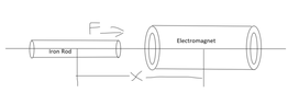
Building simulator for mass driver and need to figure out how to calculate forces on an iron rod from an electromagnet.
I am trying to build a simulator for designing a mass driver. What I am essentially doing is given an iron rod and a coil of wire, calculate the force on the iron rod at various positions along the coil axis. Ideally, I want to use the various forces to calculate the final velocity of the rod. The overall goal is to compare different windings of an coils to find the one the best accelerates the iron rod. I can then feed that final velocity back into the simulator to test accelerating the rod while its already moving (for using multiple coils in a row). I might be way out of my depth here, but what would be the formulas for these calculations? As long as there is a semi accurate way to do this, even if it is really roundabout and intensive, I can write code to do most of the work for me. For givens, I have the size and weight of the iron rod, and the inner and outer diameter, number of windings and current through the coil.

I've seen a simulator like this done before, but the person used a testing rig to find the forces rather than calculating them, and I want to avoid having to build a similar testing device as I would have to build each coil that I want to test.
I am also new here, sorry in advance if I didn't include something important. I'll be checking here often if I need to post more information.
 

Attachments

  • Diagram.png
    Diagram.png
    5.5 KB · Views: 82
Engineering news on Phys.org
I think you will need to decide how realistic you want your model to be. There are analytical formulas for the force on an iron rod inside a coil. The numerical calculations are then not difficult.
However, this will always be an idealized case; if you want a more realistic model that takes into account multiple cells etc you will need something like a FEM solver, these are far from trivial to create from scratch and you would be better off using existing software such as COMSOL or Ansys.
It is very possible that there are free software libraries around that could be used;; but they tend to have a very steep learning curve. COMSOL is -relatively speaking- easy to us (which does not mean easy)

if you
 
Thanks for the reply! I'll have to look into that software to see if it will do what I need it to. I'd like to use the analytical formulas, but since I'm trying to find force outside of the coil, I doubt they would work.
 
Hey guys. I have a question related to electricity and alternating current. Say an alien fictional society developed electricity, and settled on a standard like 73V AC current at 46 Hz. How would appliances be designed, and what impact would the lower frequency and voltage have on transformers, wiring, TVs, computers, LEDs, motors, and heating, assuming the laws of physics and technology are the same as on Earth?
While I was rolling out a shielded cable, a though came to my mind - what happens to the current flow in the cable if there came a short between the wire and the shield in both ends of the cable? For simplicity, lets assume a 1-wire copper wire wrapped in an aluminum shield. The wire and the shield has the same cross section area. There are insulating material between them, and in both ends there is a short between them. My first thought, the total resistance of the cable would be reduced...
I used to be an HVAC technician. One time I had a service call in which there was no power to the thermostat. The thermostat did not have power because the fuse in the air handler was blown. The fuse in the air handler was blown because there was a low voltage short. The rubber coating on one of the thermostat wires was chewed off by a rodent. The exposed metal in the thermostat wire was touching the metal cabinet of the air handler. This was a low voltage short. This low voltage...
Back
Top