Derivation of Vibration equation

Join the discussion
Registration is free. Start your own thread to ask a follow-up.
11 replies · 2K views · last reply
JI567
Messages
173
Reaction score
0
Can somebody please tell me what should be present in the free body diagram for this system below. Also please mention the arrow details like which direction each force in the free diagram should be acting in. I really need to understand this concept...
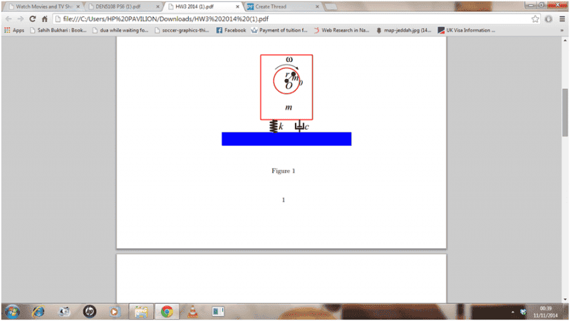
Diagram of a mass-spring-damper system with a rotating eccentric mass, labelled m, spring k, damper c, angular velocity ω, and radius r; the mass sits on a blue base, labelled Figure 1.
 
Physics news on Phys.org
You need to draw two FBDs, one for the housing and one for the rotor. Give that a shot and get back to us. It does you no good if I simply work the problem for you.
 
No. Remember Newton's Third Law. For each internal force (acting between the two bodies), you should show a force and its reaction, one on each FBD.
 
Dr.D said:
No. Remember Newton's Third Law. For each internal force (acting between the two bodies), you should show a force and its reaction, one on each FBD.

I have no idea what you are talking about. Are you talking about normal forces in each diagram acting in opposite direction to the mg? Please draw the additional arrows if that's not it
 
In the left-hand FBD, where is the force holding up the rotor?

There are other difficulties as well, but this should get you thinking..
 
You mean I need to put a centrifugal force on the left hand FBD as well? Okay alright that's fine...Is this the final FBD diagram then? Are there any other forces? Tell me if its correct or needs more forces. thanks

Free-body diagram of a rectangular block with a downward arrow labelled mg, a line labelled F = m0*r*w^2 pointing outward from the centre, and two downward arrows at the bottom labelled Kx and Cx.
Free-body diagram of a circle with a radius line from its centre, labelled F = m0*r*w^2 pointing outward along the line, a downward arrow labelled m0g at the centre, and x = r*theta labelled to the right.
 
No, it is not correct. There are additional forces required, and the ones you have are not entirely correct.
 
How can there be other forces? Could you explain. I think I have included all my forces, gravitational forces, damping force, spring force, centrifugal force. What else force do you want...unless you mean reaction forces below the Blue ground in opposite directions to the spring and damping force? Its not like I am not trying to solve this...if you see I am missing something then can you just tell me.
 
You show a force on the rotor of mo*ro*w^2 (I presume that is a force, although there is no arrow head). You show a force (a line without arrow head) on the block with the same label but in a different direction. How can this be?
 
These diagrams has to be right! There can't be anything wrong with this one now. I got the equation of motion and it makes sense. Tell me if you are still not satisfied...Let me know if you are still seeing problems

as the general equation satisfies

M*x"+c*x'+kx = Fcoswt
where F is the external force acting on the system and F = m0*r*w^2 so now I can just write the general equation of motion of the system as
(M+m0)*x"+c*x'+kx = m0*r*w^2 cos wt

Free-body diagram of a block with three downward arrows: a spring force labeled kx on the left, a damping force labeled cx' on the right, and a central arrow labeled m*x'' for the inertial force.
Hand-drawn free-body diagram of a circle with a line from its centre labelled F = m0*r*w^2 pointing up and left, a downward arrow labelled m0*x'' at the centre, and the text x = r*theta to the right.
Simple diagram of an upward-pointing arrow with the letter x written beside its shaft, indicating a positive displacement direction.
 
Looks like a step backward. You show on the rotor a force labelled m0*r*w^2 but the reaction to that force does not show on the FBD for the stator. Why is that?