evinda
Gold Member
MHB
- 3,741
- 0
Hello! (Wave)
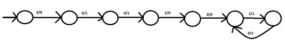
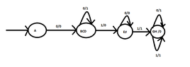
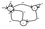
A dfa with three states has as input and output alphabet the set $\{0,1\}$.
Given the following input sequence and the corresponding output sequence , we should determine the automaton.
$ \text{ Input }: 00010101 \\ \text{Output: } 011001110$
First of all, the output should have a typo and we should ignore the last 0, so that the number of digits of the input and the output sequence is the same. Right?
Secondly, could you give me a hint how to draw such a deterministic automaton?
 ):
):