Determine angle of initial momentum in zero reference frame

  • Context: Undergrad 
  • Thread starter Thread starter rdemyan
  • Start date Start date
  • Tags Tags
    Momentum
Click For Summary

Discussion Overview

The discussion revolves around calculating the angle ##\kappa## in the context of a collision in the zero momentum reference frame (ZMF). Participants explore the implications of coordinate choice, conservation laws, and the physical meaning of angles in collision scenarios, with a focus on both theoretical and practical aspects of the problem.

Discussion Character

  • Exploratory
  • Technical explanation
  • Debate/contested
  • Mathematical reasoning

Main Points Raised

  • One participant presents the equations for transforming velocities to the ZMF and expresses confusion about calculating the angle ##\kappa##.
  • Another participant suggests that the orientation of the axes is arbitrary and proposes setting ##\kappa## to zero, noting that the problem may be underconstrained if the goal is to find rebound angles.
  • A different participant agrees with the idea of axis orientation being a choice but emphasizes the need for a non-central collision to obtain meaningful rebound directions, recommending alignment with the contact normal.
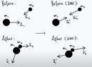
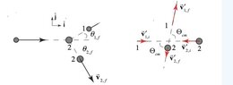
  • Further elaboration includes a reference to a video and diagrams that illustrate the transformation to the ZMF, with questions about the implications of momentum and angle definitions in the context of the problem.
  • Concerns are raised about the use of component velocities and the notation for angles in the equations provided, indicating confusion over conventions and the representation of angles in the context of the problem.

Areas of Agreement / Disagreement

Participants express differing views on the necessity of calculating the angle ##\kappa## and the implications of coordinate choice. There is no consensus on how to approach the calculation or the physical significance of the angle in the context of the collision.

Contextual Notes

Participants note limitations regarding the assumptions made about the collision type (central vs. non-central) and the definitions of angles in the equations presented. There is also uncertainty about the conventions used for representing angles and velocities in the context of the ZMF transformation.

rdemyan
Messages
67
Reaction score
4
TL;DR
How to calculate angle of zero momentum reference frame problem
I have transformed the incoming colliding objects to the zero momentum reference frame as shown in the diagram. I want to calculate the angle ##\kappa##. I don't understand how to do that. But here is what I have so far.

$$u_{com} = \frac{m_1u_1 + m_2u_2}{m_1+m_2}$$

where ##u_1,u_2## are the velocities prior to the transformation and ##u_{com}## is the center of mass velocity.

I also know that

$$u_1^{'} = u_1 - u_{com}$$

and
$$u_2^{'} = u_2 - u_{com}$$

How do I go about calculating the angle ##\kappa##?

ZMF-3-31-25.jpg
 
Last edited by a moderator:
Physics news on Phys.org
The orientation of the axes is a choice that you make, so there’s nothing to calculate. Just set ##\kappa## to zero and proceed.

Be aware that if your objective is to calculate the angle at which the two objects rebound after the collision, then the problem is underconstrained - energy and momentum are conserved no matter what the rebound angle is.
 
  • Like
Likes   Reactions: PeroK and A.T.
rdemyan said:
I want to calculate the angle ##\kappa##. I don't understand how to do that.
As @Nugatory wrote, as drawn now, it looks like a mere coordinate choice, which is likely not what you intended.

To get rebound directions that differ from 'back where you came from', you have to make the collision non-central, and provide the contact normal direction.

Then it's best to align your x-axis with that contact normal. In this coordinates ##\kappa## has a physical meaning: angle between momenta and contact normal. Then on collision, assuming no contact friction, the momenta along x are simply swaped between the objects, while along y they remain unchanged.
 
Nugatory said:
The orientation of the axes is a choice that you make, so there’s nothing to calculate. Just set ##\kappa## to zero and proceed.

Be aware that if your objective is to calculate the angle at which the two objects rebound after the collision, then the problem is underconstrained - energy and momentum are conserved no matter what the rebound angle is.
The original diagram before changing to the zero momentum frame (ZMF) is attached as the first figure to this reply. In order to understand how to switch to the zero momentum frame (ZMF) in two dimensions, I viewed a video by Dr. Ben Yelverton (see reference video below.). The second attachment is a snippet of how he setup the problem. In the first attachment it seems to me that if the momentum of stream #1 is greater than that of stream #2, the center of mass of the incoming streams would move along a line as shown in my original post. I know I didn't state that the drawing assumed that the momentum of stream #1 is greater than stream #2 in the original post.

However, it does seem that I could rotate the resulting transformation to be on the x-axis. But that should then rotate the outgoing streams as well (which outgoing streams I am not considering at the moment because I am trying to understand how this ZMF transformation works).

The third diagram is from a solution for a two dimensional problem [https://phys.libretexts.org/Bookshe..._Collisions_in_Center-of-Mass_Reference_Frame].
However, here, the incoming spheres are initially along the x-axis (one at rest). The solution continues on as follows:

Note: I know this is solution is for the angles at which the objects rebound, but I thought I could use this technique for the incoming stream angle as shown in my original post.

$$v_{1,f}^{'} = v_{1,f} - v_{cm}$$
[note: I don't know how to add the vector symbols above variables in latex].

Then, the next equations are,
$$v_{1,f}cos\theta_{1,i} = v_{1,f}^{'}cos\phi_{cm} - v_{cm}$$
$$v_{1,f}sin\theta_{1,i} = v_{1,f}^{'}sin\phi_{cm}$$

NOTE: I don't know what the latex representation for the center of mass angle shown on the drawing is, so I substituted in ##\phi##.


First off, I thought to get the final velocity, that ##v_{cm}## is added in the equation (but perhaps this is more a question of convention). An even bigger question is: shouldn't component velocities of ##v_{cm}## be used from my original post drawing for both equations? And that's where I got confused. Also, I don't know why the two equations above use ##\theta_{1,i}## when the drawing shows ##\theta_{1,f}##.

The momentum equation here is of no help because it equals zero which means that the angle will cancel out on both sides.


Attachments

  • Incoming streams.jpg
    Incoming streams.jpg
    8.3 KB · Views: 37
  • Yelverton_ZMF.jpg
    Yelverton_ZMF.jpg
    19.8 KB · Views: 68
  • physics_libre.jpg
    physics_libre.jpg
    7.2 KB · Views: 119

Similar threads

  • · Replies 30 ·
2
Replies
30
Views
2K
  • · Replies 3 ·
Replies
3
Views
1K
Replies
27
Views
1K
  • · Replies 9 ·
Replies
9
Views
1K
  • · Replies 35 ·
2
Replies
35
Views
4K
Replies
3
Views
1K
  • · Replies 3 ·
Replies
3
Views
2K
  • · Replies 12 ·
Replies
12
Views
3K
  • · Replies 6 ·
Replies
6
Views
2K
  • · Replies 42 ·
2
Replies
42
Views
4K