TPayne
- 1
- 0
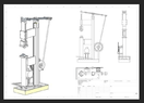
I'm building a power hammer for a buddy's forge and am working through the design phase. We are going to use a 1200lb leaf spring to actuate the upper anvil. Pretty much got the mechanical design down, but having some issues with the selection of motor and control.
The leaf spring we selected has a Spring Rate of ~300lb/in (force required to compress 1"). We would like the anvil to move 4-6" (travel of the spring is 5"--but this design pivots at CL through some pillow bearings). I feel that this means we need 1000lbf to mechanically act on the leaf spring but THROUGH a v-drive belt pulley system. I found these at automationdirect.com:
https://www.automationdirect.com/ad.../ac_motors/conveyor-z-farm_duty/mtf2-003-1b18
https://www.automationdirect.com/ad...quency_drives_(vfd)/general_purpose/gs21-23p0
We will have 230V single phase power, that's why the phase converter for a 3ph AC induction motor. I really feel like farm-duty is the way to go for the motor, but am not confident that a 3HP motor will provide enough power...especially because (with the motor speed being 1800RPM) I will be doing a speed reduction (6:1?) via the v-belt pulleys to get the RPM down. Any further speed control will be via the VFD with the goal to get all the way to <60RPM strikes at the anvil.
Before throwing $1000 at a motor and controller I wanted to see if anyone with more physics/mechanical/electrical engineering experience could confirm that this motor/controller setup I linked meets our intended needs (Listed:
-speed control down to 40RPM via VFD
-single phase 220V input
-motor HP sufficient for force required to actually strike the anvils with force
The leaf spring we selected has a Spring Rate of ~300lb/in (force required to compress 1"). We would like the anvil to move 4-6" (travel of the spring is 5"--but this design pivots at CL through some pillow bearings). I feel that this means we need 1000lbf to mechanically act on the leaf spring but THROUGH a v-drive belt pulley system. I found these at automationdirect.com:
https://www.automationdirect.com/ad.../ac_motors/conveyor-z-farm_duty/mtf2-003-1b18
https://www.automationdirect.com/ad...quency_drives_(vfd)/general_purpose/gs21-23p0
We will have 230V single phase power, that's why the phase converter for a 3ph AC induction motor. I really feel like farm-duty is the way to go for the motor, but am not confident that a 3HP motor will provide enough power...especially because (with the motor speed being 1800RPM) I will be doing a speed reduction (6:1?) via the v-belt pulleys to get the RPM down. Any further speed control will be via the VFD with the goal to get all the way to <60RPM strikes at the anvil.
Before throwing $1000 at a motor and controller I wanted to see if anyone with more physics/mechanical/electrical engineering experience could confirm that this motor/controller setup I linked meets our intended needs (Listed:
-speed control down to 40RPM via VFD
-single phase 220V input
-motor HP sufficient for force required to actually strike the anvils with force
Attachments