Did I count this current in a circuit correctly?

6 replies · 2K views · last reply
Duc Anh Le
Messages
3
Reaction score
0
This i a test question and we are not allowed to use a calculator, so I was wondering whether I did everything correctly, since the I1 = - 1/7. I am supposed to find out I3, but stopped at I1, since the result is a bit tricky.

1. Homework Statement

R1 = 10 ohm, R2 = 20 ohm, R3 = 40 ohm
I3 = ?

Homework Equations


I3 = I2 + I1
V1 = I1 * R1 + I3 * R3
V2 = R2 * I2 + I3 * R3

The Attempt at a Solution


10 = 20I1 + 40 I2 + 40I1
20 = 20I2 + 40I1 + 40I2
-10 = 70I1
I1 = -1/7
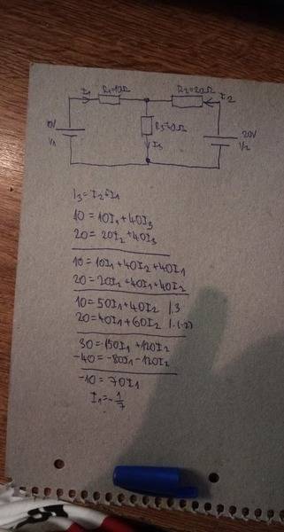
Handwritten circuit diagram with a 10V source on the left, a 20V source on the right, resistors R1 = 10 ohm, R2 = 20 ohm and R3 = 40 ohm, and branch currents I1, I2 and I3, with handwritten loop equations below.
[/B]
 
Attachments
  • Handwritten circuit diagram with a 10V source on the left, a 20V source on the right, resistors R1 = 10 ohm, R2 = 20 ohm and R3 = 40 ohm, and branch currents I1, I2 and I3, with handwritten loop equations below.
    5ly1os8imkw11.jpg
    24 KB · Views: 335
The circuit in the image is very difficult to read the component labels. Please post a closeup or draw and photograph a larger version.
Duc Anh Le said:
3. The Attempt at a Solution
10 = 20I1 + 40 I2 + 40I1
20 = 20I2 + 40I1 + 40I2
-10 = 70I1
I1 = -1/7
From what I can tell, the first term on the RHS should be 10I1 rather than 20I1. This is likely a transcription typo since your value for the current I1 looks good to me.
 
gneill said:
The circuit in the image is very difficult to read the component labels. Please post a closeup or draw and photograph a larger version.

From what I can tell, the first term on the RHS should be 10I1 rather than 20I1. This is likely a transcription typo since your value for the current I1 looks good to me.
Circuit schematic with two voltage sources, V1 at 10v on the left and V2 at 20v on the right, resistors R1 (10 Ω) and R2 (20 Ω) on the top branch, and R3 (40 Ω) in a vertical middle branch, with currents I1, I2 and I3 labelled.

Here's a better picture
 
Attachments
  • Circuit schematic with two voltage sources, V1 at 10v on the left and V2 at 20v on the right, resistors R1 (10 Ω) and R2 (20 Ω) on the top branch, and R3 (40 Ω) in a vertical middle branch, with currents I1, I2 and I3 labelled.
    6uVlA3E.png
    6 KB · Views: 371
Duc Anh Le said:
This i a test question and we are not allowed to use a calculator, so I was wondering whether I did everything correctly, since the I1 = - 1/7. I am supposed to find out I3, but stopped at I1, since the result is a bit tricky.
...

I will show that ##I_1## is negative:

$$50 I_1 + 40 I_2 = 10;\ 40 I_1 + 60 I_2 = 20 \\
5 I_1 + 4 I_2 = 1; 2 I_1 + 3 I_2 = 1\\
3 I_1 + I_2 = 0$$
Note that ##I_1## and ##I_2## have different signs and that ##I_3 = -2 I_1##, so ##I_3## and ##I_1## have different signs. And since ##I_2## is clearly positive, we know all the signs and ##I_1## is indeed negative.
 
You are on the right track, good work so far!
Do you know about Thevinin & Norton equivalent circuit transformations yet? I think they make problems like this much easier to do.
 
DaveE said:
You are on the right track, good work so far!
Do you know about Thevinin & Norton equivalent circuit transformations yet? I think they make problems like this much easier to do.
Alright, thanks for the verification. So far we've only been taught ohm's and kirchhoff's laws.