Different FEA results of the same element

Join the discussion
Ask a follow-up here, or get your own question answered by working scientists, mathematicians and engineers — people, not an autocomplete.
Real named experts · corrections over time · the nuance an AI answer skips
4 replies · 2K views
mohamadh95
Messages
43
Reaction score
0
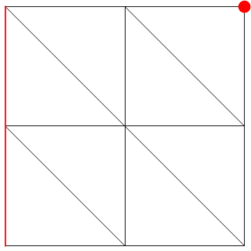
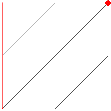
Hello. Consider the model shown below. The problem is to be solved by FEA. The plane element is constrained from moving at the red line. A concentrated load P is applied at the red point and pointing downward.
We solve the problem using the following meshes.
Untitled-1.png
f.png

Same elements are being used and the number of elements is the same in both meshes. Why the results obtained are not the same?
 
Engineering news on Phys.org
JBA said:
Are the answers different in value or in the sign?
I did an example similar to the one above with less finite elements. Here are the displacement results for an example:
IMPORTANT FEA ASSEMBLY TRIANGULAR ELEMENTS.png

The black rectangle was modeled with two triangular cst elements.
 
Did you use a different material modulus value for tension and compression on the diagonal elements? A stiffer modulus for compression than tension on the diagonal might create the type deflection difference seen. In the blue example, both the top element and the diagonal element are in tension; but, in the red example, only the top element is in tension, the diagonal element is in compression.
 
Constant Strain Triangle (CST) elements have fundamental limitations with their formulation that limits their accuracy in low-density meshes. This is due to the fact that the element's formulation assumes constant strain across the element (hence the name), sometimes resulting in reduced accuracy. CST's should only be used in models that have low strain gradients, or in high mesh densities so as to minimize strain gradients across individual elements.

See here: http://www.rpi.edu/~des/CST.ppt
rpi.edu said:
1. Use in areas where strain gradients are small
2. Use in mesh transition areas (fine mesh to coarse mesh)
3. Avoid CST in critical areas of structures (e.g., stress concentrations, edges of holes, corners)
4. In general CSTs are not recommended for general analysis purposes as a very large number of these elements are required for reasonable accuracy.

And here: https://engineering.purdue.edu/~ahvarma/CE595/CE595 Section 5.ppt
purdue.edu said:
- The CST gives good results in regions of the FE model where there is little strain gradient
- Otherwise it does not work well.