Vigardo
- 87
- 7
- TL;DR
- Would you explain why I observe weird issues in the buckling modes of a thin-walled cylindrical shell? Are they physically sound?
Dear FEA experts,
I’m trying to analyse* some finite elements model of a thin walled cylinder with variable cross-section, but I’m observing four weird issues in the buckling modes. The structure is vertically (along z-axis) and horizontally (along y-axis) loaded on top. Would you help me to understand why? Thanks!
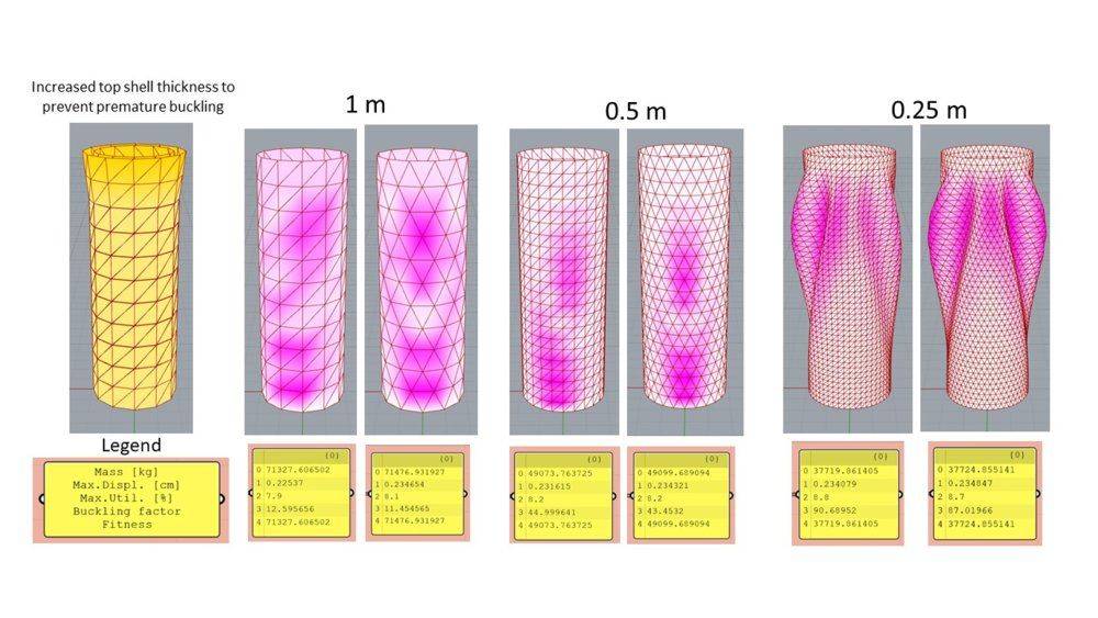
I’m trying to analyse* some finite elements model of a thin walled cylinder with variable cross-section, but I’m observing four weird issues in the buckling modes. The structure is vertically (along z-axis) and horizontally (along y-axis) loaded on top. Would you help me to understand why? Thanks!
- The lowest buckling factor (BF) increases as the mesh size decreases from 1 to 0.25 m (row number "3" in the yellow panels). Shouldn't it happen exactly the opposite? Shouldn't the structure be less stiff as element size is reduced?
- In addition, it happens an abrupt change in the lowest buckling mode shape for mesh sizes finer that 0.35 m. This is accompanied by an steady increase in BF until about 0.25 or 0.1 m element size, where it converges to around 85-90 values. Note that the observed increase in BF (issue 1.) also occurs without mode shape change.
- I tried two different triangular meshing patterns: Mesh-UV (left) and Alternate (right). It is apparent that the ripples of the first buckling mode are a bit twisted from the y-axis (green line, the direction of the horizontal load) for Mesh-UV meshing pattern. Only the Alternate meshing produces the expected horizontal ripples (because of loads symmetry). Would this be caused by the different triangular meshing?
- As expected, the maximum displacements and utilisation (row "1" and "2" in yellow panels) are the same in all of them. However, the BFs are slightly different (around 5%) between Alternate and UV meshes, even at the finer mesh size. Shouldn't they converge?