songoku
- 2,512
- 394
- Homework Statement
- Please see below
- Relevant Equations
- ##\bar x=\frac{1}{M}\int_{a}^{b}x\lambda(x)dx##
##L=I\omega##
##L=r\times p##
Conservation of linear momentum
Conservation of angular momentum
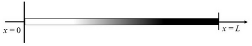
(a)
$$\bar x=\frac{\int_{0}^{L} \frac{\alpha_o}{L}x^2dx}{\int_{0}^{L}\frac{\alpha_o}{L}xdx}$$
$$=\frac{2}{3}L$$
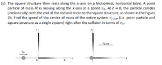
(b)
$$x=\frac{x_1+x_2}{2}=\frac{1}{6}L$$
$$y=\frac{y_1+y_2}{2}=\frac{1}{3}L$$
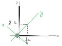
(c) I am not sure about this part. Do I need to divide the conservation of momentum into two directions?
In x-direction:
$$M.v_o\sin\theta=3M.v_{f,CM}x$$
$$v_{f,CM}x=\frac{2\sqrt{5}}{15}v_o$$
In y-direction:
$$M.v_o\cos\theta=3M.v_{f,CM}y$$
$$v_{f,CM}y=\frac{\sqrt{5}}{15}v_o$$
So:
$$v_{f,CM}=\sqrt{(v_{f,CM}x)^2+(v_{f,CM}y)^2}$$
$$=\frac{1}{3}v_o$$
Is that correct?
Thanks