Severence
- 3
- 0
Hi my names Dom, just joined the forum and look forward too getting to know you other members.
Hopefully I've posted this in the right section.
I'm struggling to understand a TMDS datasheet and was hoping someone with a bit more know-how could help me out (draw it in crayons for me) :D
I have a source device that outputs three 8bit serial RGB lines as well as clock, Hsync and Vsync. I've read through the datasheet for a SIL150A TMDS transmitter/encoder and the pinout is confusing me.
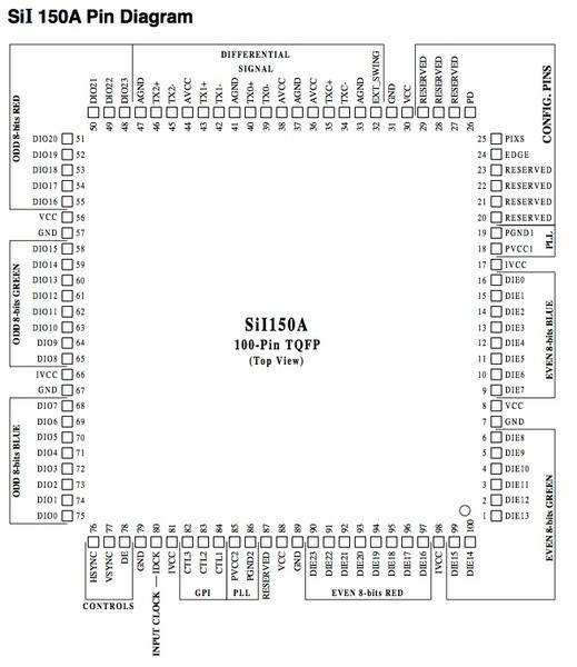
If i understand it correctly (unlikely) my serial 8 bit red signal would go to DIE23 Pin 90, green to DIE15 pin 99, and blue to DIE7 Pin 9 and this would give me 1-pixel clock input mode? input clock, HYSNC & VYSNC all seem pretty self explanatory to hook up (although I'm probably wrong about that too)
If the above is correct? what are the outputs to the corresponding inputs... for a DVI setup for example, is it TX1+ etc?
Thanks in advance to anyone who can help out.
Hopefully I've posted this in the right section.
I'm struggling to understand a TMDS datasheet and was hoping someone with a bit more know-how could help me out (draw it in crayons for me) :D
I have a source device that outputs three 8bit serial RGB lines as well as clock, Hsync and Vsync. I've read through the datasheet for a SIL150A TMDS transmitter/encoder and the pinout is confusing me.
If i understand it correctly (unlikely) my serial 8 bit red signal would go to DIE23 Pin 90, green to DIE15 pin 99, and blue to DIE7 Pin 9 and this would give me 1-pixel clock input mode? input clock, HYSNC & VYSNC all seem pretty self explanatory to hook up (although I'm probably wrong about that too)
If the above is correct? what are the outputs to the corresponding inputs... for a DVI setup for example, is it TX1+ etc?
Thanks in advance to anyone who can help out.
Attachments
Last edited:
