How does an air flow bench work

Join the discussion
Ask a follow-up here, or get your own question answered by working scientists, mathematicians and engineers — people, not an autocomplete.
Real named experts · corrections over time · the nuance an AI answer skips
4 replies · 5K views
kibestar
Messages
16
Reaction score
2
Hello, I'm new to these forums and they seemed like an excellent way to have my questions answered.

I'll start by saying that I've never had any course that dealt with fluid mechanics (mechanical engineering freshman), so I'm having quite some trouble grasping how readings on an air flow bench are to be correctly made. I'm using wikipedia's top image on its page on air flow benches to try to understand this topic:
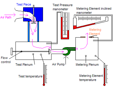
Flow_bench_schematic.GIF


Firstly, when the air pump is on, what happens with respect to pressure changes in each plenum? Is the pressure change experienced in every point inside each plenum equally, so a difference in the positioning of the manometers wouldn't cause a difference in readings? And what exact readings of the manometers and calculations would you perform to obtain the air flow volume?

I apologize for any english related mistakes, I'm not a native speaker.

Thanks in advance!
 
Physics news on Phys.org
To be accurate the pressure should be the same at all points - yes.
So you would have to wait for an equilibrium to be reached. This is easy to see - the manometer value stops changing.

All metering elements should be engineered to have a negligible impact on the performance being measured.

The exact calculations you need should be supplied with the equipment, and can vary with the equipment.
It is common these days for a computer to do that job.

But there does not need to be an equilibrium - only that the appropriate relationships are known.
These will have been determined empirically during calibration.
 
Thank you for your answer. But what if the flow bench is home made and the calculations are to be done manually? Suppose you turn the device on, disregard temperature differences between the plenums and read 'x' for the test manometer and 'y' for the metering manometer, what is to be made of those values in order to obtain flow volume? Thanks.
 
The metering element is of a know size either sharp edge orifice or straight edge orifice that is calibrateed to a know test orifice. Its Cd coefficient discharge is known.

Before and after the orifice pressure differentials is measured and air flow in CFM is calculated Testing pressure of 28inches of WC is cylinder head industry standard but testing at lower and Or high pressures can be more beneficial for testing. This will all be influence on your air supply sources capability of you apparatus? Please note its not all about higher CFM numbers? You will learn more as you go along the flow testing path. Big holes flow big numbers but don't make big power!

I have already responded to another one of your posts but here it is again.
"Hi , join <http://www.flowbenchtech.com all> the information and question/answered you have in regards to " How a flow bench works ", you will find on this fourm.
This forum is dedicated forum to flow bench design and workings.
http://www.flowbenchtech.com/forum/viewtopic.php?f=3&t=626
AND ALSO
Link to the Old Tractorsport Flowbench Forum. It is READ ONLY and is an archive only forum and can not be posted to. BUT holds valuable information on the topic of flow bench and flow testing procedures. http://www.tractorsport.com/forum/
Hope this information helps you "


Also join www.speedtalk.com a wealth of information that will be useful for you to soaurce information.

Also join www.speedtalk.com a wealth of information that will be useful for you to start your reading studys use the search function on the websites i have listed with key words of interest to you.

Get yourself pipemax software http://www.maxracesoftware.com/ and join Larry's website forum also http://maxracesoftware.com/bulletinboard/index.php?sid=0bceb2dd6ad50288b2fc0033e7ec29b8

Cheers
 
Last edited: