Modeling Air Compression Cylinder

  • #1
JeroenM
15
1
TL;DR Summary
Trying to model a piston that compresses air and pushes it out of a nozzle
Hi,

I'm have been trying to model an airsoft replica, as an electrical engineer fluid dynamics, thermodynamics is a complete new flied for me and with with help of Ai i have been learning a lot about this subject. So far I have come a long way in making something my first model sort of worked but the output energy was about 40% higher then actual measurements. So i have been trying several things to see where the losses are and how to model them using Matlab. To make things a bit simpler I removed as many components as possible to make the model in steps.

So the first part I'm now trying to model is a cylinder (with diameter of 23.85mm) with a outlet on one end that is 4.5mm in diameter and 35mm long and on the other end there is a piston which will compress the air and push it out of the smaller hole. The piston is driven by a spring (150mm spring with 692N/m springconstant and pre compressed to a length of 55mm).

So the model looks like this
3D_model_piston_cylinder.PNG


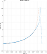
I measured the pressure inside the chamber using an absolute pressure sensor and the graph looks like this:

Pressure_measurement.png

The pressure peaks at 350kPa when the piston slams into the end of the cylinder from what I conclude is that the flow gets choked at 250kPa (more rapid rise).

From what I so far know and assume is that all the "losses" is due to the friction force of the oring (to create the seal of the piston) which is pressure depended and the fact that the air needs to be pressed through a hole. For now I modelled this using the orifice formula which i'm not sure if the correct way I also tried the sudden contraction formula but that doesn't seem to fit at all.

So I made the following code in matlab (snippet):

  1. Calculate the volume in the cylinder based on piston position (t=0 pos = 0, Lc is the cylinder length of 55mm)
  2. Calculate the pressure in the chamber using the air mass temperature and volume
  3. Calculate the temperature rise due to rapid compression
  4. Calculate the air density based on the new temperature and pressure
  5. Assume the air velocity inside the cylinder the same as the piston velocity
  6. Check if the flow is subsonic or choked flow based on the pressure of the cylinder and atmospheric pressure (P2 is assumed to be P ATM)
  7. Calculate the velocity and mass air flow through the "orifice" with either subsonic flow or choked flow. this part I'm not sure if correct because it is not really an orifice plate but more a sudden contraction to a smaller pipe (of 35mm length) in to to atmosphere but so far it seems to fit the best.
  8. Calculate the new air mass inside the cylinder
  9. Calculate the force of the spring using hooks law (1/3 of the mass is added to the total mass of the piston)
  10. Calculate the friction force of the oring based on the pressure inside the cylinder and P0 (P ATM). I use for mu a value of 2 (which seems to be way to high a value of 0.5 or lower is what I have expected) and the A_seal is the area of the oring which is for now the circumference (33.4mm) of the oring times the width (2.58mm) of the oring (also not sure if this is correct).
  11. Calculate the pressure force on the piston based on the area of the piston head and the delta pressure on the piston (P_cylinder - P0)
  12. Calculate netto force on the piston.
  13. Calculate the acceleration, velocity and position of the piston
  14. Check if piston is at the end (position > 55mm)

Simulation model:
for n = 2:n_steps
    % Chamber volume
    V_c(n) = Lc*Ap - x_p(n-1) * Ap;

    % Update chamber pressure (Ideal Gas Law)
    P(n) = m_air_chamber(n-1) * R * Temp(n-1) / V_c(n);

    Temp(n)=T*(P(n)/P0)^((gamma-1)/gamma); % Calculate temperature rise due to fast adiabatic compression
 
    % Update air density in chamber
    rho_air_chamber(n) = P(n) / (R * Temp(n));
    v_air_chamber(n) = v_p(n-1); %Air velocity in chamber same as piston

    % Density at the orifice (isentropic relationship)
    P_orifice(n) = P(n) - (0.5 * rho_air_chamber(n) * v_air_chamber(n)^2); % Simplified pressure drop to orifice
    rho_orifice = P_orifice(n) / (R * Temp(n));
  
  
    P2=P0; %P2 is Atmospheric pressure

    % Calculate orifice flow
    delta_P_orifice(n) = P(n) - P2;  % Pressure difference across orifice
    pressure_ratio = P2 / P(n);  % Downstream to upstream pressure ratio


    if pressure_ratio > critical_pressure_ratio  % Subsonic flow
        flow_regime(n) = 1;  % Subsonic
        if delta_P_orifice(n) > 0
            v_air_orifice(n) = sqrt( (2*gamma*R*Temp(n))/(gamma-1) * (1-(P2/P(n))^((gamma-1)/gamma)));
            m_dot_orifice(n) = C_d * An * P(n) * sqrt(2 / (R * Temp(n))* (gamma / (gamma - 1))  * ((P2/P(n))^(2/gamma) - (P2/P(n))^((gamma+1)/gamma)  ) );
            %*C_d_f(n)
        else
            m_dot_orifice(n) = 0;
        end
    else  % Choked flow
        flow_regime(n) = 2;  % Chokedflow_regime(n) = 2;  % Choked
        v_air_orifice(n) = sqrt(gamma*R*Temp(n)*(2/(gamma+1)));
        m_dot_orifice(n) = C_d * An *P(n)*sqrt(gamma/(R*Temp(n))) * (2/(gamma+1))^((gamma+1)/(2*(gamma-1))); 
    end

    % Update air mass in chamber and barrel
    m_air_chamber(n) = m_air_chamber(n-1) - m_dot_orifice(n) * dt;  % Air leaving chamber

    if m_air_chamber(n)<0
        m_air_chamber(n)=0;
    end


    % Spring force (Hooke's Law with pre-load)
    F_spring(n) = k * (x_preload - x_p(n-1)); % Spring force with pre-load
 
    % Friction force (based on seal)
    F_friction(n) = (P(n) - P0) * A_seal * mu;  % Friction force on the piston
  
    %Force due to pressure buildup
    F_pressure(n) = (P(n)- P0)* Ap;

    %Net force on piston
    F_n(n) = F_spring(n) - F_friction(n) - F_pressure(n);

    % Piston dynamics
    a_p(n) = F_n(n) / m_p;
    v_p(n) = v_p(n-1) + a_p(n) * dt;
    x_p(n) = x_p(n-1) + v_p(n) * dt;
  
    % Apply saturation to piston position
    if x_p(n) < 0
        x_p(n) = 0;
        v_p(n) = 0;
    elseif x_p(n) > Lc
        x_p(n) = Lc;
        v_p(n) = 0;
        break;
    end
end

So below is a picture of the simulation vs the measured data of the pressure inside the cylinder
Pressure_sim_vs_measurement.png

So the simulation is pretty close except that the peak is missing in the simulation, so either the simulation is wrong or the measurement is wrong (pressure is measure through a hole on the side of the cylinder right before the endstop).

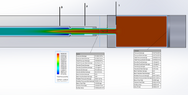
I used CFD simulation to see what I could expect and got the following results:

CFD_simulation.PNG


The inlet is a mass air flow of 50gr/s and the outlet is a static presure of 101325 pascal. From the total pressure inside the cylinder and ATM I have a pressure difference of 74kPa which I used to calculate the Coefficient of discharge value which is about 0.85. But the simulation gives different pressure values (static, dynamic, relative and total pressure) for the inlet (on the right) and the outlet (on the left) I'm not sure any more which one to use especially of the left side (pressure average is 101325, total pressure average is 151371 pascal so not sure which one to use). If use the total pressure only the pressure difference between inlet and outlet is only 23888 pascal which seems very low and would not explain why the pressure inside the cylinder is 175kPa. Here is really the lack of knowledge to understand what is happing here.

So to sum it up it up where I have my doubts:

  • Doubt if the orifice formula is the correct one, but if so not sure if i should P0 as value inside the formula especially because the choked flow seems to start at 250kPa in the measurement.
  • There is friction force inside the system but based on my model is seems to be very high, friction coefficient of 2 seems to be very high and unrealistic. Tried to simulate this using FEM but not much succes there or very low friction numbers.

Who can help me to point where I might be wrong ?

Best regards,

Jeroen
 

Attachments

  • Pressure_sim_vs_measurement.png
    Pressure_sim_vs_measurement.png
    13.8 KB · Views: 4
Last edited:
Engineering news on Phys.org
  • #2
Maybe just try to focus in on what is happening to the piston. You have a known force from the spring (at least idealistically), known piston mass. What you don't know is the contact friction force from the seal of the piston from cylinder and the internal pressure acting on the piston face. Unfortunately, I think that pressure is very complex behaviorally. My guess is the gas is basically rapidly compressing before any flow initiates. I think the flow viscosity would be critical to that.

What do you get for the pressure in the nozzle if you compress it adiabatically the initial volume cylinder + nozzle volume down to the volume of the nozzle?
 
Last edited:
  • Like
Likes JeroenM
  • #3
If the i do P1V1^1.4=P2V2^1.4 would be P1*V1^1.4/V2^1.4= 20MPa.

The part of the piston with regarding spring force and mass are easy to model but without friction of pressure it would be to fast.
 
  • #4
JeroenM said:
If the i do P1V1^1.4=P2V2^1.4 would be P1*V1^1.4/V2^1.4= 20MPa.

The part of the piston with regarding spring force and mass are easy to model but without friction of pressure it would be to fast.
Ok, so if that is correctly calculated at 20 MPa, and you are measuring peak 0.4 MPa then there must be some flow initiating prior to complete adiabatic compression of the initial volume. The question is how much because of the high level of nonlinearity...

P.s. it would be good if moving forward ( with whoever you work with) if you could type equations in Latex

Here is the code:

Code:
$$ P_1V_1^{1.4}=P_2V_2^{1.4} \implies P_1\left(\frac{V_1}{V_2} \right)^{1.4}$$

That renders as:

$$ P_1V_1^{1.4}=P_2V_2^{1.4} \implies P_2 = P_1\left(\frac{V_1}{V_2} \right)^{1.4}$$

See: LaTeX Guide
 
  • Like
Likes JeroenM
  • #5
The Darcy Weisbach Equation is developed under the assumption of steady - fully developed- incompressible flow. I have worries there for applicability to this type of problem as it is literally everything but those assumptions.

The thing is if it is reaching 0.4 MPa viscosity has to be responsible IMHO. If there were absolutely no viscosity, the gas should just slip out the barrel without a pressure gradient. However, I'm not sure to what extent purely accelerating the mass of air in front of the piston out the barrel is responsible for the pressure rise. Trying to apply Bernoulli's ( steady - inviscid flow) here to find a pressure is also a mistake in my estimation for some of the reasons above - very unmatching problem assumptions validate Bernoulli's.

I have my doubts on (certainly) my ability to produce a formula. I hope some fluids experts will chime. just thought hopefully to stimulate some thought while waiting.
 
Last edited:
  • #6
I just found an error in the mass flow rate calculation 🙈, I updated the main post. There are small differences but that the big peak is not in de simulation. Could be a measurement error.

So lets assume the calculations are correct then I still am doubting about the high friction coefficient of the oring. Im planning to make a cylinder with movable piston on 2 sides which can be pressurized to measure the friction force while under pressure.

Next step would be to add the barrel to the nozzle and model the losses there which I was planning to do based on the darcy-weisnbach and pipe-loss but as you mention that doesnt work for compressible flows. Maybe have to look more at the fanno flow model.
 
Last edited:
  • #7
JeroenM said:
There are small differences but that the big peak is not in de simulation. Could be a measurement error.
It's probably not measurement error. The piston is getting close to the end wall, and restricting the air flow through the orifice. The air flow out is restricted, the piston has inertia, so the pressure rises rapidly. It's nice to see that your pressure measurement / data acquisition has enough bandwidth to see the pressure spike.

The mechanical vibration from the piston hitting the end could cause an error in the pressure sensor. You could try isolating the sensor with a very short length of rubber hose, but the increased dead volume would cause other problems.

I did not check your calculations, but the approach you listed in Post #1 looks correct. I once wrote Matlab simulation code for a similar problem. My project was to move a 45 pound mass 9 inches in less than 150 milliseconds without slamming or bouncing. We were able to move that mass smoothly and quietly in as little as 120 msec.

My code output very nicely matched measured pressures and piston accelerations. I modelled the output as an orifice with either subsonic or choked flow. The flow restriction at end of stroke was not a problem because my model was for using an air cylinder to decelerate a moving mass, so the velocity approached zero at end of stroke. I assumed polytropic air compression. Your process happens faster, so your use of adiabatic looks good to me. My model did correctly simulate the piston bouncing off the air cushion when the output restriction was too small, and slamming into the end when the output restriction was too large.
 
  • Like
Likes AlexB23, berkeman, erobz and 1 other person
  • #8
yeah could be that it isnt an measurement error in the rest of the measurement data you can see small oscillations in pressure due to the piston bouncing, I assume the Cd value drops probably very hard at the end. What pressure value did you use for the mass flow calculation also atmospheric pressure ?

In the end application i don't see that happening at all because the pressure will be moving the bb which slows everything down. Do you known something regarding the Cd value and the flow simulations ?

This is the measurement with a barrel of 300mm connected (diameter is 6.05mm, slightly larger then the 4.5mm of the nozzle)
Sim_vs_measurement_with_barrel.png
 
Last edited:
  • #9
What is the mass of the piston, I'm trying to do some sanity check calculations?
 
  • #10
If you have access to an accelerometer, you can do a sanity check for the end of stroke pressure spike. Measure the cylinder acceleration in the direction of piston motion for a normal stroke. Locate the accelerometer as close as possible to the pressure sensor. Then tap the cylinder with a soft hammer until you can approximately duplicate the magnitude and duration of the end of stroke acceleration, while measuring the output of the pressure sensor. Remove the piston for this test. Any resulting output from the pressure sensor is due to the acceleration.

My restriction was a needle valve. I made no attempt to calculate a ##C_v## for the needle valve. We adjusted the needle valve, measured the acceleration of the system, and adjusted the polytropic coefficient and ##C_v## value in the program until the simulation results matched the measurements. The simulation results included both cylinder pressure and system acceleration. That's my recollection, this work was done 20 years ago, and all notes were left behind when I left the company.
 
  • #11
mass of the piston is 28 gram and the spring is 9 gram.

Already tried the accelerometer but data wasn't very useful or repetitive

measurement_Pressure_accelerometer.png


So what I think happens the Cd value drops when the piston comes near the end and therefor the pressure rises

Flow_restriction.PNG


Below is a plot of the complete system

BB_300mm_barrel.png
 
Last edited:
  • Like
Likes erobz
  • #12
JeroenM said:
mass of the piston is 28 gram and the spring is 9 gram.

Already tried the accelerometer but data wasn't very useful or repetitive

View attachment 355105

So what I think happens the Cd value drops when the piston comes near the end and therefor the pressure rises

View attachment 355115
Unfortunately, I don't believe the discharge coefficient ##C_d## derives from first principles with any simplicity (maybe not at all?). So, you might be stuck with empirical results or CFD models.

You seem to know how to use tech to get results, I'm not really feeling the putting much effort there. However if we just ignore compressibility, viscosity, friction, etc.( :nb) ) I get the ODE:

$$ \frac{- \pi D_p^2}{8} \rho \left( \frac{D_p^4}{D_b^4} - 1 \right) \dot x^2 + k \left( x_o - x \right) - \left( M_p + \frac{1}{3}m_s \right) \ddot x = 0 $$

Where
## D_p## Diameter of piston
##D_b## Diameter of barrel
## M_p## Mass of piston
##m_s## Mass of spring
##\rho## density of air at some point between atmospheric and 0.4MPa

I don't think its analytical, but maybe you can get AI to pump out a result numerically in a few seconds! Maybe you have done this one already - I'm just trying to hack away at it.
 
Last edited:
  • Like
Likes JeroenM
  • #13
I'm bit struggling on which mass air flow rate formula to use for my model, i have been watching and searching a lot about the formulas and there seem to be a lot of different variants. Some use the differential pressure and some use the mach number and stagnation. But since i don't know the stagnation properties (because I don't know the mach number at the orifice). I made a MATLAB script to calculate the Cd value but doesn't really seem to match with the simulation below if I do it for the 3 stages separately.

Matlab Cd script:
m_dot_simulated=0.004;

d_orifice = 6.05e-3;        %Orifice diameter
A = pi * (d_orifice/2)^2;   %Orifice Area
%%%%%%%%%%%%%%%%%%%%%%%%%%%%%%
P_in = 154776;          %inlet pressure
P_out = 144000;         %P2 pressure
V=209;        %Velocity (m/s)
%%%%%%%%%%%%%%%%%%%%%%%%%%%%%%
gamma=1.4;
T = 293;  % Temperature in Kelvin (20°C)
R = 287;  % Specific gas constant for air (J/kg·K)
% T=T*(P/101325)^((gamma-1)/gamma);

rho=P/(R*T);
ratio=P_out/P_in; %Needs to be above 0.5283

if ratio>0.5283
    m_dot = A * P_in * sqrt(gamma/(R*T)) * (P_out/P_in)^(1/gamma) * sqrt(2/(gamma-1)*(1-(P_out/P_in)^((gamma-1)/gamma)));
else
    m_dot = A * P_in * sqrt(gamma/(R*T)) * (2/(gamma+1)^(gamma+1)/(2*(gamma-1)));
end
        
C_d_orifice = m_dot_simulated/m_dot;

fprintf('Cd value for orifice: %.4f \n', C_d_orifice);
fprintf('Pressure ratio (>0.528 for subsonic): %.4f \n\n', ratio);
 

Attachments

  • CFD_sim_3_stage.PNG
    CFD_sim_3_stage.PNG
    37.7 KB · Views: 4
Last edited:
  • #14
JeroenM said:
Assume the air velocity inside the cylinder the same as the piston velocity
This would be correct only of the air were incompressible.

Have you tried first analyzing and measuring this for the case where there is no exit tube present, and the cylinder is just dead ended? That way, at least, you would eliminate the uncertainty of the exit tube. A basic principle of modeling is to simplify first before you include full complexity.

How did you describe the spring behavior, which experiences a huge compression? Did you do measurements on the spring separately? Is the mass of the spring significant? Did you do separate experiments to quantify the friction behavior of the piston. Is there significant frictional heat generation at the interface between the o-ring and the cylinder?

I would like to see the model equations you used.
 
  • Like
Likes JeroenM
  • #15
Indeed the flow pressure is probably different due to compression but it will be pretty hard to exactly know the value. Therefor I would rather use only pressures and mass flow rate to calculate everything.

But assuming there is no exit tube would mean just compressing air and the piston will stop at certain point (where Fspring = Fpressure).

All the equations I used are in the matlab code in the first post

Piston spring model:
    % Spring force (Hooke's Law with pre-load)
    F_spring(n) = k * (x_preload - x_p(n-1)); % Spring force with pre-load
 
    % Friction force (based on seal)
    F_friction(n) = (P(n) - P0) * A_seal * mu;  % Friction force on the piston
  
    %Force due to pressure buildup
    F_pressure(n) = (P(n)- P0)* Ap;

    %Net force on piston
    F_n(n) = F_spring(n) - F_friction(n) - F_pressure(n);

    % Piston dynamics
    a_p(n) = F_n(n) / m_p;
    v_p(n) = v_p(n-1) + a_p(n) * dt;
    x_p(n) = x_p(n-1) + v_p(n) * dt;

The spring force is modelled as hooks law and I measure the spring constant by compressing the spring an X amount and measuring the force required. The mass of the spring is 9 grams so that is significant to the total weight of the piston which is 28gram, from information which I could find in such cases 1/3 of the spring mass should be added to the total mass of the piston.

The friction of the O-ring due to the pressure on it i pretty significant except there are 2 variables on is the area (now assumed is circumference times the width of the oring) and a friction coefficient which seems to be 2 but I would expect between 0.4 and 0.6)

I made a test piston with 2 orings which I put under pressure with a compressor and at 300kPa in a cylinder. I measured about 16N of friction force (but this is with 2 orings and some airleakage) so it is for sure that this is a dominant part.

Oring_friction_test.jpg


and then there is the force of the compression on the piston.
 
Last edited:
  • #16
JeroenM said:
But assuming there is no exit tube would mean just compressing air and the piston will stop at certain point (where Fspring = Fpressure).
So what. This is just a test to see if you can predict the pressure vs time behavior without the exit tube present. It removes that uncertainty from the analysis. Certainly if your model for this case does not match the observed behavior, your model for the full case that includes the exit tube will not be able to match the behavior of the full model.
JeroenM said:
All the equations I used are in the matlab code in the first post
I'm not going to read them off the code. I would like to see your model equations written out using LaTeX.
JeroenM said:
The spring force is modelled as hooks law and I measure the spring constant by compressing the spring an X amount and measuring the force required.
I would like to see a graph of the spring force vs spring compression distance for several experimental data points to be sure that the relationship is indeed linear.
JeroenM said:
The mass of the spring is 9 grams so that is significant to the total weight of the piston which is 28gram, from information which I could find in such cases 1/3 of the spring mass should be added to the total mass of the piston.

The friction of the O-ring due to the pressure on it i pretty significant except there are 2 variables on is the area (now assumed is circumference times the width of the oring) and a friction coefficient which seems to be 2 but I would expect between 0.4 and 0.6)
How did you measure the normal force? Did you consider kinetic friction or only do static friction experiments? How does the coefficient of friction vary with piston velocity?
 
  • #17
Chestermiller said:
So what. This is just a test to see if you can predict the pressure vs time behavior without the exit tube present. It removes that uncertainty from the analysis. Certainly if your model for this case does not match the observed behavior, your model for the full case that includes the exit tube will not be able to match the behavior of the full model.
Yes maybe that is a good idea then I can model the friction losses better probably, will do a measurement with the end port closed and try to model that

% Spring force (Hooke's Law with pre-load)
$$F_{\text{spring}}(n) = k \cdot (x_{\text{preload}} - x_p(n-1)) % \text{Spring force with pre-load}$$

% Friction force (based on seal)
$$F_{\text{friction}}(n) = (P(n) - P_0) \cdot A_{\text{seal}} \cdot \mu % \text{Friction force on the piston}$$

% Force due to pressure buildup
$$F_{\text{pressure}}(n) = (P(n) - P_0) \cdot A_p $$

% Net force on piston
$$F_n(n) = F_{\text{spring}}(n) - F_{\text{friction}}(n) - F_{\text{pressure}}(n)$$

% Piston dynamics
$$a_p(n) = \frac{F_n(n)}{m_p}$$
$$v_p(n) = v_p(n-1) + a_p(n) \cdot \Delta t$$
$$x_p(n) = x_p(n-1) + v_p(n) \cdot \Delta t$$


Chestermiller said:
How did you measure the normal force? Did you consider kinetic friction or only do static friction experiments? How does the coefficient of friction vary with piston velocity?

I measured the force need to move the cylinder over the piston using a force meter. I can measure the Fn force because I don't know the exact friction coefficient.
 
  • #18
Simulation_vs_measurement_of_closed_cylinder.PNG

@Chestermiller this was a very good tip thank you, I added the damping factor times velocity. Only the frequency seems a bit of.

If i tune the friction coefficient to 0.5 and increase the spring constant from 692N/mm (which i measured with force meter) and change it to 735N/mm even the frequency now perfectly matches.

Simulation_vs_measurement_of_closed_cylinder_adjusted.PNG
 
  • #19
JeroenM said:
Yes maybe that is a good idea then I can model the friction losses better probably, will do a measurement with the end port closed and try to model that

% Spring force (Hooke's Law with pre-load)
$$F_{\text{spring}}(n) = k \cdot (x_{\text{preload}} - x_p(n-1)) % \text{Spring force with pre-load}$$

% Friction force (based on seal)
$$F_{\text{friction}}(n) = (P(n) - P_0) \cdot A_{\text{seal}} \cdot \mu % \text{Friction force on the piston}$$
The normal force at the wall is not based on the gas pressure. It is based on the force fit of the o-ring (which is constant).

Is the region behind the piston where the spring is located open to the atmosphere, or is it a closed chamber?
 
  • Like
Likes erobz
  • #20
In this case due to the design of the piston most of normal force is dependent on the pressure, because when the piston is moving the air will push the oring to the cylinder wall. On the front of the piston there are small hole that channel the air to the inside of the oring. So when the piston moves back there is no air seal anymore and then only the normal force die to the force fit is present.

1000036635.jpg

On the bottom you can see the Green Line of the contact area of the oring when the pressure is remove the Green Line disappears.

This is what the section view looks like.
1000036636.jpg


The backside of the piston is open to atmosphere
 
  • #21
Tried adding adiabatic temperature rise but seems it is not happening

Simulation with static tempeature
Closed_port_static_temp.PNG


Simulation with adiabatic temperature rise

$$\text{Temp}(n) = T \left(\frac{P(n)}{P_0}\right)^{\frac{\gamma - 1}{\gamma}}$$

Closed_port_addiabatic_rise_temp.PNG


If I remove the friction force and increase the piston weight to 31.7gram (instead of the 28 grams measured) i can get it to match using adiabatic temperature rise:
Closed_port_addiabatic_rise_temp_no_oring_increased_mass.PNG


Temperature rise in kelvin
adiabatic_temp_rise.PNG
 
Last edited:
  • #22
The analysis of the exit pipe is a little problematic. Its L/D ratio is only 7.8 which is less than the hydrodynamic entrance length for both laminar and turbulent air flow. This means that the Hagen Poiseulle equation (for laminar flow) or the Darcy-Weisbach correlation (for turbulent flow) will be inaccurate for flow in this pipe, even if we could consider the instantaneous flow occurring to be at quasi steady state. It would probably be better to use the orifice equation for the entrance to the pipe and neglect the viscous drag within the pipe itself.
 
  • Like
Likes JeroenM
  • #23
I found a mistake with the friction that I forgot the sign when velocity is negative

Still had to tune the mass to 31gram instead of 28gram but that is acceptable, the friction coefficient is now 0.49 which is in the range of what I would expect.
Closed_port_addiabatic_rise_temp_increased_mass.PNG


For the second simulation I have now these results using the follwing mass flow rate formula:

For subsonic flow
$$
\text{m_dot_orifice}(n) = C_d \cdot A \cdot P(n) \cdot \sqrt{\frac{2}{R \cdot T(n)} \cdot \frac{\gamma}{\gamma - 1} \left(\left(\frac{P_0}{P(n)}\right)^{\frac{2}{\gamma}} - \left(\frac{P_0}{P(n)}\right)^{\frac{\gamma + 1}{\gamma}}\right)}
$$

Pressure_sim_vs_measurement_update.png


It is not a perfect match but I think at the and the Cd values changes a lot when the piston near the end.

For the complete simulation including the ball in the barrel the pressure exactly matches the measurement (bottom left graph). But i think that the BB leaves the barrel 3ms earlier in the simulation then in reality. So either the pressure is lower in the barrel or the BB sees another counter acting force. I thought maybe the air mass that is in the barrel in front of the BB at t=0 is being compressed which decreases the net force on the BB. But not sure how to model that maybe it is the air friction using the darcy-weisbach. I ordered an light sensor to measure the exact moment the BB leaves the barrel.

Complete simulation.PNG
 
  • #24
JeroenM said:
I found a mistake with the friction that I forgot the sign when velocity is negative

Still had to tune the mass to 31gram instead of 28gram but that is acceptable, the friction coefficient is now 0.49 which is in the range of what I would expect.
View attachment 355403

For the second simulation I have now these results using the follwing mass flow rate formula:

For subsonic flow
$$
\text{m_dot_orifice}(n) = C_d \cdot A \cdot P(n) \cdot \sqrt{\frac{2}{R \cdot T(n)} \cdot \frac{\gamma}{\gamma - 1} \left(\left(\frac{P_0}{P(n)}\right)^{\frac{2}{\gamma}} - \left(\frac{P_0}{P(n)}\right)^{\frac{\gamma + 1}{\gamma}}\right)}
$$

View attachment 355404

It is not a perfect match but I think at the and the Cd values changes a lot when the piston near the end.

For the complete simulation including the ball in the barrel the pressure exactly matches the measurement (bottom left graph). But i think that the BB leaves the barrel 3ms earlier in the simulation then in reality. So either the pressure is lower in the barrel or the BB sees another counter acting force. I thought maybe the air mass that is in the barrel in front of the BB at t=0 is being compressed which decreases the net force on the BB. But not sure how to model that maybe it is the air friction using the darcy-weisbach. I ordered an light sensor to measure the exact moment the BB leaves the barrel.

View attachment 355405
Are you accounting for accelerating the mass of the BB and how that effects chamber pressure? Btw your graphs are all pretty small to be readable.
 
Last edited:
  • #25
This is the model for the BB
$$F_{\text{drag}} = 0.5 \cdot C_{d_{\text{sphere}}} \cdot \rho_{\text{air_atm}} \cdot v_b(n)^2 \cdot A_{\text{bb}}$$
$$F_{bb}(n) = (P_{\text{barrel}}(n) - P_{\text{atm}} )\cdot A_{\text{bb}} - F_{\text{drag}}$$
$$a_{b_{\text{drag}}} = \frac{F_{bb}(n)}{m_b}$$
$$v_b(n) = v_b(n-1) + a_{b_{\text{drag}}} \cdot \Delta t$$
$$x_b(n) = x_b(n-1) + v_b(n) \cdot \Delta t$$

So either P_barrel is lower or P_atm should be function.

So in the simulation the BB exits at point 1, but I think in reality the BB exits at point 2 because of the steeper pressure drop (this I will verify with the light sensor).
pressure.PNG
 
  • #26
JeroenM said:
This is the model for the BB
$$F_{\text{drag}} = 0.5 \cdot C_{d_{\text{sphere}}} \cdot \rho_{\text{air_atm}} \cdot v_b(n)^2 \cdot A_{\text{bb}}$$
$$F_{bb}(n) = (P_{\text{barrel}}(n) - P_{\text{atm}} )\cdot A_{\text{bb}} - F_{\text{drag}}$$
$$a_{b_{\text{drag}}} = \frac{F_{bb}(n)}{m_b}$$
$$v_b(n) = v_b(n-1) + a_{b_{\text{drag}}} \cdot \Delta t$$
$$x_b(n) = x_b(n-1) + v_b(n) \cdot \Delta t$$

So either P_barrel is lower or P_atm should be function.

So in the simulation the BB exits at point 1, but I think in reality the BB exits at point 2 because of the steeper pressure drop (this I will verify with the light sensor).
I don't think we have drag acting on the BB per se (assuming it's a close fit). There is no flow around it, especially not opposite its motion. There is surely a pressure ahead of it from it accelerating the viscous air out of the barrel that is in front of it. I'm just wondering if that "Drag force" you have in there is results without sound reason.

The way I see this is there are 4 systems to write equations for:

1) Air between the BB and the barrel exit
2) BB itself
3) Air between the BB and Piston
4) Piston/ "massive" spring itself

Have you incorporated all the EOM interdependencies for each system? I'm not saying what you are doing is wrong, but can we say its correct?
 
Last edited:
  • #27
For the section 1) If we very imprecisely apply the momentum equation ignoring viscosity, and assume incompressible flow:

1736182864405.png


$$ \sum \boldsymbol F = \frac{d}{dt} \int_{cv} \rho \boldsymbol{v} d V\llap{-} + \int_{cs} \rho \boldsymbol{v} \left( \boldsymbol{V} \cdot d \boldsymbol{A} \right) $$

Since we aren't varying the cross sectional area (or the density across the control volume - incompressible flow assumption) the control surface terms on the right sum to zero.

And we are left with (one dimensional):

$$ \left( P_i - P_{atm} \right) A = \frac{d}{dt} \int_{cv} \rho v ~d V\llap{-} $$

$$ \left( P_i - P_{atm} \right) = \rho \frac{d}{dt} \left( -\dot z \int dz \right) \tag{1}$$

Taking the derivative:

$$ \implies P_i = P_{atm} - \rho \left( \dot z^2 + z \ddot z \right) $$

( I'm not certain on the sign - I think ##\ddot z < 0 ( \dot {\boldsymbol{v}} = -\ddot z \boldsymbol{ \hat{z}} ) ##, hence the negative term )

##z## is the length of the barrel ahead of the projectile
##P_i## is the pressure acting on the projectile from ahead

Even with this basic assumption model we still get pressures to analyze that retard the motion of the projectile.

If you want to add frictio with some kind of Darcy Weisbach relation you are going to add that term to the left hand side of (1)

$$ \left( P_i - P_{atm} \right) -\beta( z,\dot z ) \dot z^2 = -\rho \frac{d}{dt} \left( \dot z ~z\right) \tag{1}$$

Where ##\beta ( z, \dot z )## is that whole factor out front that has dependencies on the speed of the gas ##\dot z ## ( via friction factor), and the instantaneous length of the remaining gas in the end of the barrel ##z##. It's probably not valid, but I believe it would be something like that for the end of the barrel.
 
Last edited:
  • #28
I believe I was sloppy in deriving (1). I would instead take ##z## as originating from the barrel entrance:

1736217039764.png


Now the equation becomes:

$$ \begin{align}P_i A - P_{atm}A &= \rho A \frac{d}{dt} \left( \dot z \int_{z}^{L} dz \right) \tag{}
\\&= \rho A \frac{d}{dt} \left( \dot z L - \dot z z \right) \tag{}
\\&= \rho A \left( L-z \right) \ddot z - \rho A \dot z^2 \tag{} \end{align} $$


I hope someone can verify that the math appears to be sensible.

EDIT: I don't like the term ##-\rho A \dot z^2##. If I go ahead and look at Newtons second for a force ##F## acting on the projectile from the chamber:

$$ F - P_iA = m \ddot z $$

If I sub in ##P_i A## I get something that seems wrong for the EOM:

$$ F - P_{atm}A - \rho A \ddot z (L-z) + \rho A \dot z^2 = m \ddot z $$

That last term on the LHS is very suspicious because it is the same direction as ##F##, and I expect all forces other than ##F## to be resistive in nature.

Anyone see the mistake I'm making?
 
Last edited:
  • #29
erobz said:
I believe I was sloppy in deriving (1). I would instead take ##z## as originating from the barrel entrance:

View attachment 355451

Now the equation becomes:

$$ \begin{align}P_i A - P_{atm}A &= \rho A \frac{d}{dt} \left( \dot z \int_{z}^{L} dz \right) \tag{}
\\&= \rho A \frac{d}{dt} \left( \dot z L - \dot z z \right) \tag{}
\\&= \rho A \left( L-z \right) \ddot z - \rho A \dot z^2 \tag{} \end{align} $$


I hope someone can verify that the math appears to be sensible.

EDIT: I don't like the term ##-\rho A \dot z^2##. If I go ahead and look at Newtons second for a force ##F## acting on the projectile from the chamber:

$$ F - P_iA = m \ddot z $$

If I sub in ##P_i A## I get something that seems wrong for the EOM:

$$ F - P_{atm}A - \rho A \ddot z (L-z) + \rho A \dot z^2 = m \ddot z $$

That last term on the LHS is very suspicious because it is the same direction as ##F##, and I expect all forces other than ##F## to be resistive in nature.

Anyone see the mistake I'm making?
This is not a force balance on the piston; it seems to be a force balance on the gas.
 
  • #30
Let x be the distance between the piston face and the end of the cylinder connected to the exit tube, let L be the total length of the large chamber minus the piston thickness, d be the unstretched length of the spring, Then, at time t, the length of the spring is L-x and the amount of spring compression is (d-(L-x))=d-L+x. If we orient the system, such that the closed end of the cylinder is to the left, and the exit tube is to the right, the force that the spring exerts on the left face of the piston is ##k(d-L+x)## and the acceleration of the piston towards the right is ##-\frac{d^2x}{dt^2}## The force balance on the piston is then $$-M\frac{d^2x}{dt^2}=k(d-L+x)-(P-P_{atm})A$$or $$M\frac{d^2x}{dt^2}=-k(d-L+x)+(P-P_{atm})A$$where A is the cross sectional area of the piston, M is the mass of the piston, and P(t) is the pressure in the large chamber.

Application of the open system version of the first law of thermodynamics to the chamber control volume tells us that $$\frac{P}{P_0}=\left(\frac{m}{m_0}\frac{x_0}{x}\right)^{\gamma}$$ and $$\frac{T}{T_0}=\left(\frac{m}{m_0}\frac{x_0}{x}\right)^{\gamma-1}$$where m is the mass of air in the chamber at time t.

To be Continued
 
  • #31
Chestermiller said:
This is not a force balance on the piston; it seems to be a force balance on the gas.
The equation with ##F## involved is meant to be Newtons 2nd Law applied to the projectile. I'm just trying to look at some barrel effects as the projectile pushes the gas out of it.

I tried the "Energy Equation" too for the force balance on the gas:

$$ \dot Q - \dot W_s = \frac{d}{dt} \int_{cv} \left( \frac{V^2}{2} + gh + u \right) \rho ~dV\llap{-} + \int_{cs} \left( \frac{V^2}{2} + gh + u + \frac{P}{\rho} \right) \rho \boldsymbol{V} \cdot d \boldsymbol{A} $$

And I get a slightly different term:

$$ 0 = \frac{d}{dt} \int_{cv} \left( \frac{V^2}{2} \right) \rho ~dV\llap{-} + P_{atm} V A - P_i V A $$

$$ 0 = \rho A \frac{d}{dt} \left( \frac{V^2}{2} \int_{z}^{L} dz \right) + P_{atm} V A - P_i V A $$

$$ 0 = \rho A \left( V \dot V \left( L - z \right) - \frac{V^2}{2} \dot z \right) + P_{atm} V A - P_i V A $$

Now divide everything through by ##VA##, ## V = \dot z ## and move ##P_i## to LHS:

$$ P_i = P_{atm} + \rho \left( \ddot z \left( L - z \right) - \frac{1}{2} \dot z ^2 \right) $$

Now if you compare with the result for ##P_i## in post 28 I see that there is now a factor of ##\frac{1}{2}## that shows up the ##\dot z ^2 ##...

Now if you flip to the free body of the projectile being pushed by some arbitrary force ##F## (this would be the compressed gas behind it) for the sake of argument it's the same result ...almost...

$$ F - P_{atm}A - \rho A \ddot z (L-z) + \rho A \frac{1}{2} \dot z^2 = m \ddot z $$

The factor of ##1/2## that appears when using Energy is somewhat concerning - but I've seen that discrepancy between momentum and energy analysis with chains being accelerated from rest in these forums, but it is not as concerning as why the ##\dot z^2## term appears to aide ##F##? The fact that the control volume is losing mass is somehow helping ##F## via ##\dot z##. Is that real or mistake?
 
  • #32
erobz said:
The equation with ##F## involved is meant to be Newtons 2nd Law applied to the projectile. I'm just trying to look at some barrel effects as the projectile pushes the gas out of it.

I tried the "Energy Equation" too for the force balance on the gas:

$$ \dot Q - \dot W_s = \frac{d}{dt} \int_{cv} \left( \frac{V^2}{2} + gh + u \right) \rho ~dV\llap{-} + \int_{cs} \left( \frac{V^2}{2} + gh + u + \frac{P}{\rho} \right) \rho \boldsymbol{V} \cdot d \boldsymbol{A} $$

And I get a slightly different term:

$$ 0 = \frac{d}{dt} \int_{cv} \left( \frac{V^2}{2} \right) \rho ~dV\llap{-} + P_{atm} V A - P_i V A $$

$$ 0 = \rho A \frac{d}{dt} \left( \frac{V^2}{2} \int_{z}^{L} dz \right) + P_{atm} V A - P_i V A $$

$$ 0 = \rho A \left( V \dot V \left( L - z \right) - \frac{V^2}{2} \dot z \right) + P_{atm} V A - P_i V A $$

Now divide everything through by ##VA##, ## V = \dot z ## and move ##P_i## to LHS:

$$ P_i = P_{atm} + \rho \left( \ddot z \left( L - z \right) - \frac{1}{2} \dot z ^2 \right) $$

Now if you compare with the result for ##P_i## in post 28 I see that there is now a factor of ##\frac{1}{2}## that shows up the ##\dot z ^2 ##...

Now if you flip to the free body of the projectile being pushed by some arbitrary force ##F## (this would be the compressed gas behind it) for the sake of argument it's the same result ...almost...

$$ F - P_{atm}A - \rho A \ddot z (L-z) + \rho A \frac{1}{2} \dot z^2 = m \ddot z $$

The factor of ##1/2## that appears when using Energy is somewhat concerning - but I've seen that discrepancy between momentum and energy analysis with chains being accelerated from rest in these forums, but it is not as concerning as why the ##\dot z^2## term appears to aide ##F##? The fact that the control volume is losing mass is somehow helping ##F## via ##\dot z##. Is that real or mistake?
Sorry, I don't follow. The analysis I did so far was application of the first law of thermodynamics to the gas in the chamber (control value) and a force balance on the piston. Later, when I have time, I will provide the analysis of the (Bernoulli equation for the mechanical energy balance on the overall air in the chamber and exit tube.
 
  • #33
Chestermiller said:
Sorry, I don't follow. The analysis I did so far was application of the first law of thermodynamics to the gas in the chamber (control value) and a force balance on the piston. Later, when I have time, I will provide the analysis of the (Bernoulli equation for the mechanical energy balance on the overall air in the chamber and exit tube.
I was just playing around with deriving how much pressure the projectile sees from in front of it. It is clearing the barrel as it is traveling along its length and both accelerating and discharging mass in front of it. I'm running into some theoretical questions along the way.

If the notation I'm using is foreign I will show more steps and assumptions?
 
  • #34
erobz said:
I was just playing around with deriving how much pressure the projectile sees from in front of it. It is clearing the barrel as it is traveling along its length and both accelerating and discharging mass in front of it. I'm running into some theoretical questions along the way.

If the notation I'm using is foreign I will show more steps and assumptions?
Oh. I was analyzing the original problem
 
  • Like
Likes erobz
  • #35
UThis is a continuation of the analysis I presented in post #30. It is for the case of an inviscid gas, without piston friction (temporarily). It addresses the situation submitted by the OP in post #1.

The present analysis uses the subscript C to represent the parameter values in the large chamber, T to represent the parameter values in the exit tube, and zero to represent parameter values at time zero.

The part of analysis for the transition from the large chamber to the exit tube make use of the Bernoulli equation and the assumption of quasi steady state for the flow. Under this assumption, we obtain (The detailed analysis is in the book Introduction to Chemical Engineering Thermodynamics by Smith and Van Ness):$$u_2^2-u_1^2=\frac{2P_Cv_C\gamma}{\gamma-1}\left[1-\left(\frac{P_{atm}}{P_C}\right)^{\frac{\gamma-1}{\gamma}}\right]$$where ##u_1=-\frac{dx}{dt}## is the velocity of the piston, ##u_2## is the discharge velocity at the exit of the tube, and ##v_C=\frac{A_C x}{m}## is the specific volume of the air in the chamber. To get the mass discharge rate of air coming out the exit of the tube, we multiply the air velocity at the tube exit ##u_2## by the density of the air in the tube ##1/v_T## and the cross sectional area of the tube ##A_T## to obtain $$\dot{m}=-\frac{u_2A_T}{v_T}$$The specific volume of the air at the exit of the tube is related to the specific volume of the air in the chamber by: $$v_T=v_C\left(\frac{P_{atm}}{P_C}\right)^{1/\gamma} $$

Now to summarize. We have 3 coupled first order ordinary equations in time to solve for the three dependent variables m, x, and u (where u is the velocity of the piston): $$\frac{dm}{dt}=\dot{m}=-\frac{u_2A_T}{v_T}$$ $$\frac{dx}{dt}=-u_1$$and $$M\frac{du_1}{dt}=k(d-L+x)-(P_C-P_{atm})A$$
 
Last edited:
Back
Top