twiztidmxcn
- 43
- 0
Doin a question based around RC circuits and was in a bit of a bind, lookin for some help.
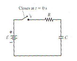
The capacitor in the figure below begins to charge after the switch closes at t = 0s.
a) what is deltaVc when t >> 0 after switch is closed?
b) what is Qmax in terms of emf, R and C?
c) in this circuit, does I = + dQ/dt or - dQ/dt?
d) find an expression for the current at time t. graph I from t=0 to t=5tau
A) for this part, i just said that when the switch is closed, the emf causes a current to flow and charge to build on the plates of the capacitor. the resistor slows this down but eventually, the plates reach their maximum charge capacity and the potential difference across them is equal to the emf. delta Vc = E (emf)
I believe that is the reason why, any extra info would be helpful
B) Wasn't sure how to do this. I know the equations are Qmax = C*(delta Vc)max = C * E (emf)
also know that Q = Qmax * (1 - e^(-t/tau)) where tau = RC
I'm attempting to relate R, C AND E (emf) all at the same time like the question asks, but i don't think they can be related to Qmax all in one equation.
C) Since this is a 'upside down' decay graph for Q, I = + dQ/dt. The slope is always positive but it decreases to zero as time approaches infinite. it means current is always flowing into the wire until infinite, where current stops flowing.
D) i took the expression, Q = Qmax * (1 - e^(-t/tau)) and took its derivative, dQ/dt, giving me dQ/dt = (Qmax/tau)*e^(-t/tau) where tau = RC.
right direction? totally wrong?
The capacitor in the figure below begins to charge after the switch closes at t = 0s.
a) what is deltaVc when t >> 0 after switch is closed?
b) what is Qmax in terms of emf, R and C?
c) in this circuit, does I = + dQ/dt or - dQ/dt?
d) find an expression for the current at time t. graph I from t=0 to t=5tau
A) for this part, i just said that when the switch is closed, the emf causes a current to flow and charge to build on the plates of the capacitor. the resistor slows this down but eventually, the plates reach their maximum charge capacity and the potential difference across them is equal to the emf. delta Vc = E (emf)
I believe that is the reason why, any extra info would be helpful
B) Wasn't sure how to do this. I know the equations are Qmax = C*(delta Vc)max = C * E (emf)
also know that Q = Qmax * (1 - e^(-t/tau)) where tau = RC
I'm attempting to relate R, C AND E (emf) all at the same time like the question asks, but i don't think they can be related to Qmax all in one equation.
C) Since this is a 'upside down' decay graph for Q, I = + dQ/dt. The slope is always positive but it decreases to zero as time approaches infinite. it means current is always flowing into the wire until infinite, where current stops flowing.
D) i took the expression, Q = Qmax * (1 - e^(-t/tau)) and took its derivative, dQ/dt, giving me dQ/dt = (Qmax/tau)*e^(-t/tau) where tau = RC.
right direction? totally wrong?
Last edited: