How does the double-slit pattern change depending on the slits?

Join the discussion
Ask a follow-up here, or get your own question answered by working scientists, mathematicians and engineers — people, not an autocomplete.
Real named experts · corrections over time · the nuance an AI answer skips
30 replies · 7K views
Ad VanderVen
Messages
169
Reaction score
13
Summary:: How does the double slit pattern change in the double slit experiment depending on the width of the slits and their spacing?

On Wikipedia in the article Double-slit experiment, the lower figure of the figure next to the Overview chapter shows a picture of what can be seen when two slits are used. The lower figure, entitled Double-slit pattern, shows vertical lines, which decrease in brightness the further away from the center they are. This pattern seems to repeat itself left and right, but with decreasing line brightness. My first question is whether it is indeed true that the pattern repeats itself. My second question is how the pattern changes as the width of the slits increases and my third and final question is what happens as the distance between the slits increases.
 
Physics news on Phys.org
The pattern changes depending on the shape, size, and number of slits. Unfortunately I'm about to head to bed and couldn't quickly find a good source for you. If no one has provided a good source by tomorrow I'll see what I can find.
 
PeroK said:
Try this:


This video only shows the relation between the distance of the slits from the screen and the double slit pattern. My main interest is the relation between the width of the slits and the double slit pattern and the relation between their spacing and the double slit pattern.
 
Ad VanderVen said:
This video only shows the relation between the distance of the slits from the screen and the double slit pattern. My main interest is the relation between the width of the slits and the double slit pattern and the relation between their spacing and the double slit pattern.
If you are able to watch all 8 minutes, he covers everything. Including the effect of slit separation right at the end.
 
I watched the video to the end and it is shown that there is a proportional relationship between fringe width (w) and screen distance (D): w = (lambda/s) D or w/D = lambda/s, where s represents slit separation and lambda represents wavelength. The formula shows that there is also a proportional relationship between w and s. The video does not cover the influence of slit width.
 
  • Sad
Likes   Reactions: PeroK
Ad VanderVen said:
he video does not cover the influence of slit width.
Here's a simulation of the double slit experiment where you can adjust the slit width, slit spacing, and several other parameters: https://physics.bu.edu/~duffy/HTML5/double_slit.html
Just click the double slit button near the bottom and then adjust the sliders.
 
  • Like
Likes   Reactions: Melbourne Guy, Motore and PeroK
It's worth noting that there's no quantum mechanics involved in calculating how the size, shape, and position of the slits affects the interference pattern - this is all classical wave mechanics that was known and well understood a century before QM. The specifically quantum mechanical thing here is that we get to apply wave mechanics even when we're sending particles towards the slits.
 
  • Like
Likes   Reactions: Lord Jestocost, vanhees71 and PeterDonis
Dear Drakkith

The animation at http://physics.bu.edu/~duffy/HTML5/double_slit.html is very enlightening. But I won't really understand it until I know the formula for the chart in red in the Type of opening: Double Slit setting. Can you give the formula for the function associated with that graph, preferably in terms of the Slit width (micrometers), Distance between slits (micrometers) en Distance to the screen (meters).
 
  • Like
Likes   Reactions: vanhees71
Drakkith said:
Here's a simulation of the double slit experiment
Thanks, @Drakkith, it never occurred to me before playing with the simulator that different wavelengths would produce different width results on the screen 🤦‍♂️
 
  • Like
Likes   Reactions: vanhees71
Ad VanderVen said:
Dear Drakkith

The animation at http://physics.bu.edu/~duffy/HTML5/double_slit.html is very enlightening. But I won't really understand it until I know the formula for the chart in red in the Type of opening: Double Slit setting. Can you give the formula for the function associated with that graph, preferably in terms of the Slit width (micrometers), Distance between slits (micrometers) en Distance to the screen (meters).
I cannot, as I don't know the math behind it.
 
Lord Jestocost said:
The resulting pattern is a product of the double slit interference pattern and the single slit diffraction pattern:
http://lampx.tugraz.at/~hadley/physikm/apps/2single_slit.en.php

Thanks a lot for this site. On the website at the bottom is a graph of how in Young's double slit experiment the function of I/I<\sub>0<sub> depends on y. But what exactly does the formula for this chart look like?
 
Lord Jestocost said:
The formula and the corresponding definitions are specified above the chart.
It is written: "Two slits separated by a distance d that each have a width a display a diffraction pattern that is a product of the double slit interference pattern and the single slit diffraction pattern."

I do not see anywhere the formula for 'the double slit interference pattern' and the formula for 'the single slit diffraction pattern'.
 
Drakkith said:
I cannot, as I don't know the math behind it.
Thanks a lot for your sincere answer. You are a real scientist. A real scientist knows when he/she doesn't know.
 
Ad VanderVen said:
I do not see anywhere the formula for 'the double slit interference pattern' and the formula for 'the single slit diffraction pattern'.
Take the appropriate limits: ##a \rightarrow 0## and ##d\rightarrow 0## will show the results you require.
 
Ad VanderVen said:
I do not see anywhere the formula for 'the double slit interference pattern' and the formula for 'the single slit diffraction pattern'.
On http://lampx.tugraz.at/~hadley/physikm/apps/2single_slit.en.php you find the follwing formula for the overall pattern:

Unbenannt.PNG

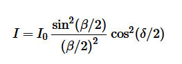
The first term refers to the “single slit diffraction pattern”, the second term ##cos^2(\delta/2)## to the “double slit interference pattern”.
 

Attachments

  • Unbenannt.PNG
    Unbenannt.PNG
    2.2 KB · Views: 192
  • Like
Likes   Reactions: Drakkith and PeroK
From the result in http://lampx.tugraz.at/~hadley/physikm/apps/2single_slit.en.php as mentioned earlier
$$\large I=I_0\frac{\sin^2(\beta/2)}{(\beta/2)^2}\cos^2(\delta/2)$$
I note in addition to the zero limits for a and d giving the two factors I note that that setting a=d corresponds to a single slit of size 2a
In Xray crystallography these two factors are known as the structure factor (from the lattice geometry) and the form factor (from the details of the atomic scattering) and this is a very useful characteristic.
 
  • Like
Likes   Reactions: Lord Jestocost and PeroK
Lord Jestocost said:
On http://lampx.tugraz.at/~hadley/physikm/apps/2single_slit.en.php you find the follwing formula for the overall pattern:

View attachment 295773
The first term refers to the “single slit diffraction pattern”, the second term ##cos^2(\delta/2)## to the “double slit interference pattern”.
I had, of course, seen that formula. But I didn't see that the formula was a function. Normally you have y=f(x) , where y is the dependent variable and x is the independent variable. Apparently I is the dependent variable, but what is the independent variable and what exactly is it's support? If you give I<sub>0<\sub>, beta and delta a value, the result is a constant. By the way, what does I<sub>0<\sub> represent?
 
Lord Jestocost said:
On http://lampx.tugraz.at/~hadley/physikm/apps/2single_slit.en.php you find the follwing formula for the overall pattern:

View attachment 295773
The first term refers to the “single slit diffraction pattern”, the second term ##cos^2(\delta/2)## to the “double slit interference pattern”.
I assume the formula can also be rewritten as follows:
$$\displaystyle { I_{{0}} \frac {\sin^{2} \left( x \right) } {{x}^{2}}} \cos^{2} \left( bx \right)$$
with
$$\displaystyle x\, = \,\beta/2$$
and
$$\displaystyle bx=\delta/2$$
But what is then the support of x?
 
The diffraction pattern in the case of Fraunhofer diffraction (light source as well as detection screen "infinitely far away" from the slits) is very intuitive: The amplitude is the Fourier transform of the slits. That makes it clear that the double-slit amplitude is the sum of two single-slit amplitudes with the phase-shifts due to the (relative) placement of the two slits. The intensity then is the (modulus) squared amplitude.
 
  • Like
Likes   Reactions: PeroK and Lord Jestocost
Lord Jestocost said:
On http://lampx.tugraz.at/~hadley/physikm/apps/2single_slit.en.php you find the follwing formula for the overall pattern:

View attachment 295773
The first term refers to the “single slit diffraction pattern”, the second term ##cos^2(\delta/2)## to the “double slit interference pattern”.
Using the transformation I suggested, where
$$\displaystyle \beta\, = \,2\,x$$
and
$$\displaystyle \delta\, = \,2\,bx$$
one obtains:
$$\displaystyle \int_{-\infty }^{\infty }\!{\frac { \left( \sin \left( x \right) \right) ^{2} \left( \cos \left( bx \right) \right) ^{2}}{{x}^{2}}}\,{\rm d}x=\pi /2$$
as a result of which
$$\displaystyle { I_{{0}}\frac { \left( \sin \left( x \right) \right) ^{2} \left( \cos \left( bx \right) \right) ^{ 2}}{{x}^{2}}}$$
with
$$\displaystyle I_{{0}}\, = \, \frac{2}{\pi }$$
is a proper probability density function with support $$x \in \mathbb{R}$$.

Am I correct?
 
Last edited:
hutchphd said:
From the article

We define δ=2πdsin(θ)/λ and β=2πasin(θ)/λ.

So to be pedantic ##\theta## is the independent variable; ##I## is the dependent value and the rest are parameters/
Thanks for the clarification.
 
Lord Jestocost said:
The resulting pattern is a product of the double slit interference pattern and the single slit diffraction pattern:
http://lampx.tugraz.at/~hadley/physikm/apps/2single_slit.en.php

The formula they give is as follows:
$$\displaystyle I \, = \,4\, I_{{0}} \, {\frac{\left( \sin \left( \beta/2 \right) \right) ^{2} \left( \cos \left( \delta/2 \right) \right) ^{2}}{{\beta}^{2}}}$$
with
$$\displaystyle \delta\, := \,2\,{\frac {\pi \,d\sin \left( \theta \right) }{\lambda}}$$
and
$$\displaystyle \beta\, := \,2\,{\frac {\pi \,a\sin \left( \theta \right) }{\lambda}}$$
Therefore, $$I$$ is a function of $$\theta$$. What exactly is the support of $$\theta$$?
 
The site:

http://lampx.tugraz.at/~hadley/physikm/apps/2single_slit.en.php

has a figure at the bottom where ##\frac {I}{I_{0}}## is depicted as a function of ##y## but ##y## is not defined on the site. What does ##y## stand for, what is the support of ##y## and what is exactly the formula for the function ##f(y)## in ##\frac {I}{I_{0}}=f(y)##?
 
Last edited: