- 30,548
- 7,530
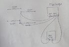
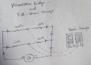
That may be because you have not read more about potential dividers (and possibly not much about electrical circuits at all?). The idea of a potential divider is to arrange two resistors so that the voltage at their mid point is what you want. You have a formula, in the link I gave you and everywhere else that discusses potential dividers. Where did the idea of a 10k pot come from? What. voltage would you expect with that as R1? If you want to use a variable resistor for adjustment then you need to have a series fixed resistor to limit the maximum current to something safe.Micheal_Leo said:i am very much confused
Use the formula to make an equation with just one unknown (the required R1) and three knowns: Vsupply, Vbridge (=1V) and R2.
With 1V applied to the 120Ω bridge, you will have a sensible current. (Work it out)
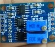
The vendor can't be relied on to know any electronics at all; he may just be retailing meaningless (to him) components. The Power dissipated by a resistor value R, with I current flowing is P = I2R. What does that work out as for 250mA?Micheal_Leo said:Edit: today the vender told me that
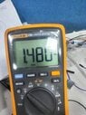
How were you planning to do that?Micheal_Leo said:yes i believe 250mA is still high , i will go for 5-20mA first
Is your interest here in the results of a mechanical measurement exercise, rather than an electronics project? What is your level of expertise here? It may be better to go for another measurement method or even to buy a unit that works 'on its own' and will interface with your Arduino.