How to increase the stiffness of a simple structure

Join the discussion
Ask a follow-up here, or get your own question answered by working scientists, mathematicians and engineers — people, not an autocomplete.
Real named experts · corrections over time · the nuance an AI answer skips
7 replies · 4K views
omarmorocci
Messages
47
Reaction score
0
Hello everybody,

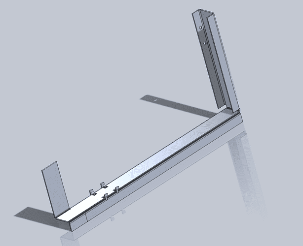
I am currently working on desinging a tool, and I would like to get your advice on how to increase it's stiffness.
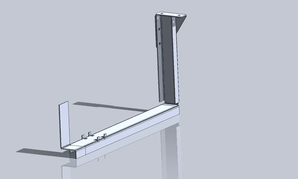
upload_2017-5-29_16-53-46.png


The tool will be used for correct positioning of a component.
It consists of 2 parts :
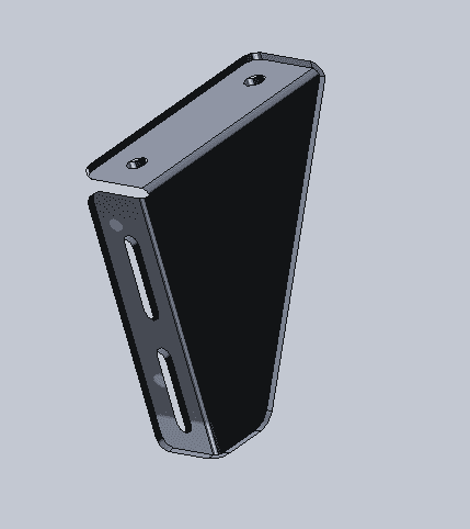
upload_2017-5-29_16-54-47.png

And
upload_2017-5-29_16-55-4.png
 
Physics news on Phys.org
Way too little information. In which plane does it need to be stiffer? Any limitations on materials? Manufacturing techniques? Cost?

Simple answer might be to make it out of tubes rather than sheet.
 
Nidum said:
Need some more information . What is the component being held and how is the holding tool supported ?
Part one is connection the main frame via nuts and bolts
Part two has 4 teeth like structures that hangs onto the main frame

CWatters said:
Way too little information. In which plane does it need to be stiffer? Any limitations on materials? Manufacturing techniques? Cost?

Simple answer might be to make it out of tubes rather than sheet.
Direction.png

The only important direction is the one shown via the arrow.
Material is either sheet metal or aluminium.
no limitation on manufacturing techniques
Cost should be under 50 euros
 
CWatters said:
I'm afraid I still can't really visualise what's fixed and where the load is in relation to that fixed point.
I will post a complete picture tomorrow to show exactly how everything's connected
 
CWatters said:
I'm afraid I still can't really visualise what's fixed and where the load is in relation to that fixed point.

This is how the tool is connectec to the rail.
There is no load on it. The only requirement is that it's position along the rail should not exceed +- 5mm
Capture1.PNG
Capture2.PNG

Capture3.PNG
 

Attachments

  • Capture1.PNG
    Capture1.PNG
    6.6 KB · Views: 564
  • Capture2.PNG
    Capture2.PNG
    23.9 KB · Views: 575
How is the end of the fixture with the tested part vertically supported and what is the weight load on the fixture from the tested part?

If there is any friction force in the direction you indicate then there is no provision in the fixture to prevent the fixture from twisting the vertical attachment arm of the fixture and deflecting the arm in the direction of the load you indicate.