Hydraulic lifting force of this arrangement of pipes

Click For Summary
SUMMARY

The discussion centers on calculating hydraulic lifting forces in a system of pipes using Pascal's principle. The output force F2 is determined to be 400 N when the input force F1 is 100 N and the area ratio A2/A1 is 4. However, the output forces F3 and F4 are not equal to F2 due to the varying cross-sectional areas and the need to account for the volume of fluid displaced. The key takeaway is that while hydrostatic pressures may be equal, the forces differ based on the areas over which they act.

PREREQUISITES
  • Understanding of Pascal's principle in fluid mechanics
  • Knowledge of hydraulic systems and their components
  • Familiarity with concepts of force, area, and pressure
  • Basic principles of work and energy in fluid dynamics
NEXT STEPS
  • Study the derivation of Pascal's principle in hydraulic systems
  • Learn about the relationship between pressure, area, and force in hydraulic applications
  • Explore the calculations involved in fluid displacement and volume flow rates
  • Investigate the effects of varying cross-sectional areas on hydraulic performance
USEFUL FOR

Engineers, fluid mechanics students, and professionals working with hydraulic systems will benefit from this discussion, particularly those involved in designing or analyzing hydraulic lifting mechanisms.

ucody0911
Messages
21
Reaction score
2
Homework Statement
hydraulic lifting
Relevant Equations
pascal
Hello All, :)

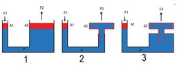
Please see the picture , input force F1 and area A1 and second area A2 are all same for 3 cases .
in case 2 and 3 , red open outline represents a free-to-move , ie , "T" piece move upward
for the 1st case , output force F2 should be F2=A2/A1 x F1 , by pascal's principle ,
what about output forces of F3 and F4 ? can be same as F2 ? how i calculate them ?

thanks
 

Attachments

  • hyd lift.jpg
    hyd lift.jpg
    15 KB · Views: 123
Last edited by a moderator:
Physics news on Phys.org
For F3 and F4, one must include the force downward on the red outline in the diagrams that have regions of fluid above the red parts.
 
Last edited:
Work in = Work out
Force in x Delta height in = Force out x Delta height out

Piston diameter x Delta height = Displaced volume

Displaced volume in = Displaced volume out
Piston diameter in x Delta height in = Piston diameter out x Delta height out

Note that the top volume of the T shape does not change as the machine operates.
 
T piece is just hollow piston , therefore hydraulic pushing force exerted on upper side of T piston which has top area of A2
 
ucody0911 said:
T piece is just hollow piston , therefore hydraulic pushing force exerted on upper side of T piston which has top area of A2
And a bottom area nearly as great.
 
  • Like
Likes   Reactions: Lnewqban
ucody0911 said:
T piece is just hollow piston , therefore hydraulic pushing force exerted on upper side of T piston which has top area of A2
Correct.
But that hydraulic pushing force exerted on upper side of hollow T piston, which has top area of A2, can't do any work.
The T-shaped piston is a single piece which surfaces can't move respect to each other (just like it happens to a pressurized gas tank).
The sliding telescopic portion, which cross section has a smaller area than the top surface A2, can move and do the lifting work.
 
so then what is the amount of force F2 and F3 ?
 
ucody0911 said:
so then what is the amount of force F2 and F3 ?
Post #3 gives you the easy way to solve these.
Consider how much the right hand top surface rises for a given depression of the left hand top surface.
 
  • Like
Likes   Reactions: Lnewqban
consider , left side depression and right side rises are same for all 3 cases , and A2/A1 = 4 , F1 =100 N
then F2 will be 400 N for 1 st case .
F3 and F4 will same as 400 N ?
 
  • #10
ucody0911 said:
left side depression and right side rises are same for all 3 cases
No.
If LHS goes down x, what volume flows across to the RHS?
If RHS goes up y, what extra volume is there on the RHS in each case?
 
  • Like
Likes   Reactions: Lnewqban
  • #11
haruspex said:
No.
If LHS goes down x, what volume flows across to the RHS?
If RHS goes up y, what extra volume is there on the RHS in each case?
of course , RHS upwards forces depends volume flows and LHS depressions
i just wanted clarify that those F2 , F3 and F4 forces are equal like hydrostatic forces of previous talked subject .
Replied as all 3 hydrostatic forces are equal,
now here in this case , downward hydrostatic pressure replaced by upward hydraulic pressure , same in principal , therefore i thought that F2, F3 , F4 are equal,
if not equal , why ?
 

Attachments

  • hydforce.jpg
    hydforce.jpg
    46.8 KB · Views: 138
Last edited:
  • #12
ucody0911 said:
if not equal , why ?
For the same reason that F1 and F2 are not equal. The hydrostatic pressures are equal there, but the forces are different because the pressure acts over different areas.

To avoid the complication introduced by the varying cross sections on the right hand sides, the easiest way is to think about work done when there is a small vertical displacement. In figure 1, if the LHS moves down x, it displaces volume xA1. So that much fluid flows to the right. How much will the RHS rise? Since the work done must be the same each side, how high does the RHS rise?

Apply the same analysis to the other diagrams.
 

Similar threads

  • · Replies 2 ·
Replies
2
Views
3K
  • · Replies 4 ·
Replies
4
Views
1K
  • · Replies 3 ·
Replies
3
Views
3K
  • · Replies 3 ·
Replies
3
Views
2K
  • · Replies 1 ·
Replies
1
Views
2K
  • · Replies 2 ·
Replies
2
Views
2K
  • · Replies 11 ·
Replies
11
Views
3K
  • · Replies 1 ·
Replies
1
Views
6K
  • · Replies 2 ·
Replies
2
Views
8K
  • · Replies 21 ·
Replies
21
Views
8K