Homework Help Overview
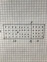
The discussion revolves around the induced current in a wire loop that is situated within a changing magnetic field. Participants are exploring the implications of electromotive forces (EMFs) and resistances in a circuit model, questioning the setup and calculations involved in determining the total resistance and current flow.
Discussion Character
Approaches and Questions Raised
- Participants are examining different circuit models, including lumped circuit representations with multiple EMF sources. There are discussions about the calculation of total resistance and the effects of opposing EMFs on current direction and magnitude.
Discussion Status
The conversation is ongoing, with various interpretations of the circuit and its components being explored. Some participants have offered alternative models and calculations, while others express uncertainty about the correctness of their approaches. There is no explicit consensus on the correct method or outcome yet.
Contextual Notes
Some participants note potential arithmetic mistakes and question the assumptions made in the circuit models. There are references to specific values and configurations that may not be fully clarified, contributing to the complexity of the discussion.