arestes
- 84
- 4
- Homework Statement
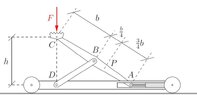
- A mobile jack is operated using a hydraulic cylinder, which can be used to adjust the horizontal position of point A:
1. Calculate the force acting on the hydraulic cylinder using the principle of virtual work. To do this, first design a simple beam model of the jack and insert suitable supports at points A and D.
2. Calculate the shear force and the internal moment at point P using the principle of virtual work. To do this, the previously introduced support at point A must be appropriately modified.
- Relevant Equations
- Principle of VIRTUAL WORK + Polplan (Instantaneous centers of rotations and "Nebenpole" if there's a translation for that). I need to justify all virtual displacements with this Polplan
Hello
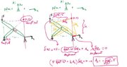
I did part 1 of this HW using the rules for findint Instantaneous Center of Rotations in STATICS (Hauptpol in german) and Nebenpol (idk how to translate it). I attached my calculation and it's supposed to be the right answer. I replaced the two forces on A (piston force Ah and vertical reaction Av) by a single valued suppor (with Av) and a force Ah which I treat as not being part of the support, leaving the support free to slide. This is the method I was taught. Then I apply rules to find the ICR (Hauptpole): for example, assuming that point B is a Nebenpol (1,2) then (0,1) - (1,2) and (2,0) should lie on the same line, but on the other hand, the perpendicular support at A means that the (2,0) Hauptpol should lie on the line perpendicular to the movement of that support (vertical line then) and (0,2) is found. The rest is geometry to make small displacements.
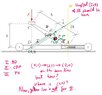
Part 2 throws me off. I need to find internal moment, normal and shear using this method, for which I make a cut but I need to add a certain type of "Gelenk". For example, for the moment, I add an articulation (which is a Gelenk with 0 moment) and this splits the bar ABC in two: ABP and PA.
Now, how am I going to find the ICR (Hauptpol) for member ABP?
Questions:
1) is point B really a "NebenPol"? (one connecting DB and ABC) I've only seen Nebenpole between links from end to end, not a connection in the middle of another member.
2) How do I find ICR (0,1), (0,2) and (0,3)?
I know I can find the results making cuts and applying equilibrium equations. I am being forced to solve it using Polplan (ICR) and virtual work.
Any help would be appreciated
I did part 1 of this HW using the rules for findint Instantaneous Center of Rotations in STATICS (Hauptpol in german) and Nebenpol (idk how to translate it). I attached my calculation and it's supposed to be the right answer. I replaced the two forces on A (piston force Ah and vertical reaction Av) by a single valued suppor (with Av) and a force Ah which I treat as not being part of the support, leaving the support free to slide. This is the method I was taught. Then I apply rules to find the ICR (Hauptpole): for example, assuming that point B is a Nebenpol (1,2) then (0,1) - (1,2) and (2,0) should lie on the same line, but on the other hand, the perpendicular support at A means that the (2,0) Hauptpol should lie on the line perpendicular to the movement of that support (vertical line then) and (0,2) is found. The rest is geometry to make small displacements.
Part 2 throws me off. I need to find internal moment, normal and shear using this method, for which I make a cut but I need to add a certain type of "Gelenk". For example, for the moment, I add an articulation (which is a Gelenk with 0 moment) and this splits the bar ABC in two: ABP and PA.
Now, how am I going to find the ICR (Hauptpol) for member ABP?
Questions:
1) is point B really a "NebenPol"? (one connecting DB and ABC) I've only seen Nebenpole between links from end to end, not a connection in the middle of another member.
2) How do I find ICR (0,1), (0,2) and (0,3)?
I know I can find the results making cuts and applying equilibrium equations. I am being forced to solve it using Polplan (ICR) and virtual work.
Any help would be appreciated