Interfacing of NTC thermistor with microcontroller

Join the discussion
Ask a follow-up here, or get your own question answered by working scientists, mathematicians and engineers — people, not an autocomplete.
Real named experts · corrections over time · the nuance an AI answer skips
15 replies · 3K views
PhysicsTest
Messages
260
Reaction score
27
Homework Statement
I want to understand the circuit for the NTC interfacing with the microcontroller
Relevant Equations
Voltage divider equation = V*R2/(R1+R2)
I am trying to understand a circuit where the NTC thermistor is interfaced with micro controller, but i am not able to understand the voltage output at 25DegC. According to the ST website the output of the circuit is 1.4V but as per my calculations it is 1.05V, i am not sure why. Please help.
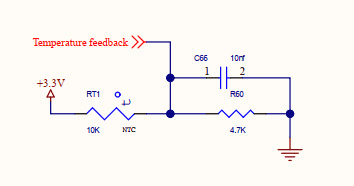
1672152854535.png

My understanding is since it is 10K NTC thermistor at 25DegC the resistance is 10K. Is this assumption correct?
V_TempFeedback = 3.3 * 4.7/(10+4.7) = 3.3*4.7/14.7 = 1.055V.
 
Physics news on Phys.org
What is connected to the "Temperature feedback" net? Can you post a link to the ST website where they show this circuit? Thanks.
 
Page no 6 and 4 to the micro. There is a software to be installed motor workbench in that it shows
1672154796997.png
 
I never checked that i will check and update.
 
I guess if it's just an ADC input, it should be pretty high impedance compared to the NTC circuit. I don't have any ideas why they show a different value of the voltage divider output...
 
1) Your voltage divider calculation is correct, for the circuit as shown.
2) 10Kohm @ 25C is an extremely common thermistor value.
3) 1.4V to the ADC would correspond to 6.38Kohm for the thermistor. Assuming a high impedance input, which is almost always true.
4) I am suspicious of the "NTC thermistor info" given. Thermistors aren't specified by a voltage value unless an associated circuit is given. Whoever wrote this part seems to care more about software than hardware.
5) People/Companies make mistakes. Things can be misinterpreted.
6) You are stuck without a thermistor part number and a specification. Either you or ST is reporting inconsistent information. We can't figure it out either, without a research project that we all are unlikely to take on.
 
Reply
  • Like
Likes   Reactions: berkeman
If two changes were made to the circuit, ST engineers would almost certainly have checked the numbers. So I look for single changes that could explain the difference.

If a different supply voltage to 3.3 volt, had been used, then Vs = 4.375 volt.
That is too far from any regular voltage, so is most unlikely.

If a different value fixed resistor had been used, then Rf = 7.368k
That is not an E value I recognise, so I keep the value 4k7.

If a different value thermistor had been used, then Rt = 6.378k @ 25 °C.
A value most unexpected for a thermistor.

So I can see no single change to the circuit that plausibly explains the change.
That only leaves us with a hypothetical error by a human.

1.4 only contains two significant digits. The A-D should give 3 digits.
What if the voltage had been read by the A-D converter as 1.04 volts.
Given a temperature error, that is close to the calculated 1.055 volts.
Then a typo removed the 0 to make it 1.4 volts in the documentation.
 
Reply
  • Informative
Likes   Reactions: berkeman
I tried searching for another evaluation board to compare it, i found some useful information. On page14 found the following information
The document link evspin
1672239159896.png

1672239196029.png


If i do the calculations as per the equation
T = R40 = 4.7K = 4700
VREFP = 3.3V
VPC4 = 1.05V (as per ST it was 1.4V
then i get around 23.85DegC more or less equal to 25DegC.
 
You might also check the tolerance of the NTC, they are often rated ±10% to ±20%. That would certainly cover the observed "error."
 
Reply
  • Like
Likes   Reactions: PhysicsTest
Tom.G said:
You might also check the tolerance of the NTC, they are often rated ±10% to ±20%. That would certainly cover the observed "error."
Except that there are no observations in this case. It's all paperwork so far, I think.
 
Wait, is the original note maybe saying that it's 1.4Vmax @ 70C? (to be sure the ADC input voltage is within its valid range)

1672327537186.png
 
berkeman said:
Wait, is the original note maybe saying that it's 1.4Vmax @ 70C? (to be sure the ADC input voltage is within its valid range)

View attachment 319509
I read that as the maximum thermistor temperature.

Additionally supported by post #12 above.