Inventor wanting to start prototyping

  • Topic: Construction 
  • Thread starter Deleted member 656102
  • Start date
11 replies · 4K views · last reply
Deleted member 656102
Hello. My name is Robert, I am 30 and i have been an inventor for 10 years.

I have been developing ideas to the thinnest details. Unfortunately, my life was a little hard and i don't have a mechanical/physical/electrical/ background. But i get a lot work done without that. I design 3D's of some of my projects, even tried some animations, but keep getting stuck with free versions of programs... I want to talk with some experts in diy field, i want to start my projects and make some prototypes, i even plan on buying a 3D printer.

3D render of several cylindrical water wheels with wooden spoke ends and bluish-grey slatted drums, mounted on dark brown curved frames over a flat grey base.


Up in the picture is my first project for presentation, a water turbine for river bottoms with a water flow blocker, or it can be used as a VAWT, in the picture bellow,
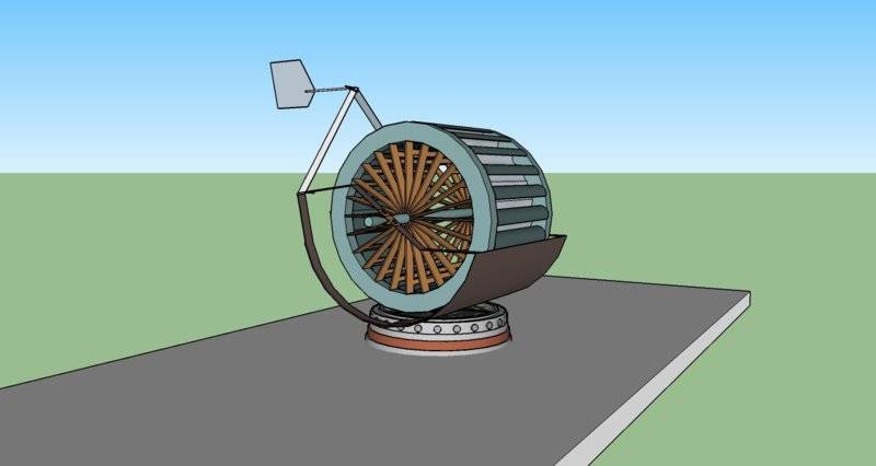
3D rendering of a cylindrical turbine on a circular base, with wooden-colored radial blades inside a light blue frame, a dark curved housing at the bottom, and a flat fin on a bent arm at the top left.
with a blocker that moves (rotates on a bearing using wind fin)
Air, water, who cares, as long as it gives green power.

The blocker is used to stop the water/air forcing the turbine in the wrong direction.

Ok, so This is enough for today, i have a lot of amasing stuff, and this is just one design, i would really like some comments, so, please, comment. Thanks for reading.

Edit: Just realized that the system with the fin can be used on river bottoms with changing flow directions..
 
Attachments
  • 3D render of several cylindrical water wheels with wooden spoke ends and bluish-grey slatted drums, mounted on dark brown curved frames over a flat grey base.
    Picture 1.jpg
    40.5 KB · Views: 912
  • 3D rendering of a cylindrical turbine on a circular base, with wooden-colored radial blades inside a light blue frame, a dark curved housing at the bottom, and a flat fin on a bent arm at the top left.
    Picture 2..jpg
    21 KB · Views: 807
Last edited by a moderator:
Welcome to the PF, Robert. :smile:

So far I'm not understanding the use of the "blocker" part. It seems like it will always be in the way, preventing the paddlewheels from being turned by flowing water. Can you show a sketch of one in a river with flowing water to clarify that?

Also, are you familiar with the difference in efficiency between a paddlewheel design and a propeller design? Why is the propeller design for wind/water generators usually so much more efficient? :smile:

https://i.pinimg.com/236x/60/35/c2/...2103--solar-power-sustainable-engineering.jpg

Photo of a blue cylindrical water turbine with a paddlewheel-style rotor, suspended by green straps from a crane arm over a river.
 
Attachments
  • Photo of a blue cylindrical water turbine with a paddlewheel-style rotor, suspended by green straps from a crane arm over a river.
    6035c2b7d54b7e428c12cc8416762103--solar-power-sustainable-engineering.jpg
    13.6 KB · Views: 874
Blocker is used because only 1/4 of this type of turbine is active. The other 1/4 is proactive, it blocks the spinning because it rotates in the different direction.

https://www.alibaba.com/product-detail/River-Water-Turbine-Generator-Slow-Water_60714293750.html

I just found this online. Quite a price they got.

Edit: turns out the water turbine already exists..

But, the wind turbine i haven't seen, at least not like this. This is unique.
I have seen only a plan for some students in Nova Scotia to make experiments..

Edit 2: I calculate wind turbines by amount of space they take up. So if you have a classic vertical turbine, its 5 meters tall and the blades another square meter., that's a lot of space :D
 
Last edited by a moderator:
There are many designs of water turbines, each optimum within a specific range of pressure difference and flow rate.

Water wheels are one, kaplan turbines, frances turbines, propeller turbines, Tyson turbine, pelton wheels.helical turbines, cross flow turbines, screw turbines, Jonval turbine, Turgo turbine. That list is not complete. Wikipedia has descriptions and pictures of most of them.

Display board of four red water turbine runners: a Pelton wheel, a Francis turbine, a second Francis turbine and a Kaplan turbine, each labelled with its name and specific speed.


To get people to be interested in your design, you'll have to be able to answer questions. How much pressure? How much flow? What RPM? What is the best case efficiency? You'll need a textbook and some study to be able to do that.
 
Attachments
  • Display board of four red water turbine runners: a Pelton wheel, a Francis turbine, a second Francis turbine and a Kaplan turbine, each labelled with its name and specific speed.
    Water_turbine_runners.jpg
    21.3 KB · Views: 1,056
  • Like
Likes   Reactions: berkeman
anorlunda said:
There are many designs of water turbines, each optimum within a specific range of pressure difference and flow rate.

Water wheels are one, kaplan turbines, frances turbines, propeller turbines, Tyson turbine, pelton wheels.helical turbines, cross flow turbines, screw turbines, Jonval turbine, Turgo turbine. That list is not complete. Wikipedia has descriptions and pictures of most of them.

View attachment 237270

To get people to be interested in your design, you'll have to be able to answer questions. How much pressure? How much flow? What RPM? What is the best case efficiency? You'll need a textbook and some study to be able to do that.

I have no idea about physics calculations, flow, pressure or anything.

Further, neither do i plan on learning physics from scratch, which would take me years, since i don't know basics of math neither.

So actually, i was thinking more about talking of this particular idea, ways of improving it, advantages and disadvantages, how to build it... simple stuff like that.
 
berkeman said:
Welcome to the PF, Robert. :smile:

So far I'm not understanding the use of the "blocker" part. It seems like it will always be in the way, preventing the paddlewheels from being turned by flowing water. Can you show a sketch of one in a river with flowing water to clarify that?

View attachment 237264

So this is a windmill.
3D sketch of a vertical-axis wind turbine on a round base, with a wooden-spoked rotor inside a light blue housing, a white and a grey arrow showing airflow, orange curved arrows showing rotation, and a flat vane on a bent arm.

White arrow is turning it. Orange arrows are the way it rotates. The blue arrow is hitting the blocker because if it would hit the paddle wheel it would push it in the opposite direction that it should go.
 
Attachments
  • 3D sketch of a vertical-axis wind turbine on a round base, with a wooden-spoked rotor inside a light blue housing, a white and a grey arrow showing airflow, orange curved arrows showing rotation, and a flat vane on a bent arm.
    ffff.jpg
    29.2 KB · Views: 747
Robert Petrusic said:
I have no idea about physics calculations, flow, pressure or anything.

Further, neither do i plan on learning physics from scratch, which would take me years, since i don't know basics of math neither.

So actually, i was thinking more about talking of this particular idea, ways of improving it, advantages and disadvantages, how to build it... simple stuff like that.

I am afraid this is self contradictory.

You can't improve a design without understanding why it works (or doesn't work) nor without understanding how to compare different designs in terms of efficiency - which requires math. And physics. Otherwise you will be mostly wasting time :frown:

Please remember there is already tons of knowledge, people have spent millions of hours optimizing turbine designs using sophisticated math models. Just logic is not enough to beat them.
 
  • Like
Likes   Reactions: davenn and russ_watters
Borek said:
I am afraid this is self contradictory.

You can't improve a design without understanding why it works (or doesn't work) nor without understanding how to compare different designs in terms of efficiency - which requires math. And physics. Otherwise you will be mostly wasting time :frown:

Please remember there is already tons of knowledge, people have spent millions of hours optimizing turbine designs using sophisticated math models. Just logic is not enough to beat them.

I didnt say i don't understand physics.

And about logic, i guess i am Don Quijot. Fighting the impossible odds. No i don't believe its impossible, i am a genius, don't see why it should be so hard.

I designed kinetic harvester for running, couple years later us army published the exact same thing for replacing batteries.
 
One hour walking can fully charge 4 cellphones. And that's only using your knee.
 
You haven't answered:
anorlunda said:
To get people to be interested in your design, you'll have to be able to answer questions. How much pressure? How much flow? What RPM? What is the best case efficiency?
which is needed to convince others from your idea.
Robert Petrusic said:
I use only logic and experience, common knowledge is an unknown.
You can do that, but you cannot expect that others will fill the gaps for you and do the hard part of it.
Robert Petrusic said:
No i don't believe its impossible, i am a genius, don't see why it should be so hard.
A mentor of mine once said: "A genius is not the guy with the brilliant idea at night. It is the one who sits at the desk the very next morning and elaborates his idea!"
Borek said:
Please remember there is already tons of knowledge, people have spent millions of hours optimizing turbine designs using sophisticated math models. Just logic is not enough to beat them.
This is a serious hint. Especially propelling systems translate directly into real big money. You bet they know what's the best propelling system possible depending on several dozens of parameters.
Robert Petrusic said:
One hour walking can fully charge 4 cellphones. And that's only using your knee.
But 100 posts on the internet cannot replace hard calculations, and one hour thinking cannot charge you with an entire book on fluid dynamics.

I think the case is clear so far, i.e. answered within the general unspecific limits given from the OP. We cannot teach neither classical mechanics nor fluid dynamics here, and we definitely cannot compete with professional shipyards and their capacities to solve propelling problems.

This thread remains closed.
 
  • Like
Likes   Reactions: davenn