Kirchoff's Law Problem about this Induction Generator circuit

In summary: I'm looking at the wrong current direction. Yes, the third equation looks to be correct.Sorry about that. I was looking at your Option #2 and comparing it to Option #1 from post #5. I've been working on this for a few days and I've confused myself. Sorry about that. I'll quit now before I make any more mistakes. You seem to have things well in hand. Good luck with the rest of your studies.
  • #1
Martin Harris
103
6
Homework Statement
Find currents Is (stator current), Ir (rotor current) and Im (magnetic current)
Relevant Equations
Kirchoff's Law
Ohm's Law
Hi,
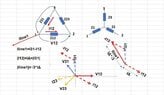
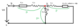
Please find attached below the Induction Generator circuit.
I have the following parameters:
ParameterValue
Rs = Rr (Resistance on stator and rotor)0.2 Ω
Ls = Lr (inductance on stator and rotor)5 mH = 0.005 H
p (number of pairs of poles)2
f (frequency)60 Hz
Vsl (stator line voltage) - delta connection220 V
s (slip of the generator)-0.02

I am requested to find the currents.

Kirchoff's Law Im = Is + Ir
$$Is = \frac{Vsl} { Zoverall} $$
$$Zoverall = Zs+Zparallel$$
$$Zs = Rs+iXs = 0.2+1.8849 Ω $$
$$Zm = iXm = (0+37.6991i) Ω $$
$$Zr = \frac {Rr} {s} + iXr = (-10 +1.8849i)Ω $$
$$Zparallel = \frac {Zm*Zr} {Zm+Zr} = \frac { (0+37.6991i)*(-10 +1.8849i)} {(0+37.6991i)+(-10 +1.8849i)} $$
$$Zparallel = (-8.5261+3.9490i) Ω $$

Hence $$Zoverall = Zs+Zparallel = (0.2+1.8849 Ω) + (-8.5261+3.9490i) Ω $$
$$Zoverall =(-8.3261+5.8339i)$$

$$Is = \frac{220V} {-8.3261+5.8339i } $$
$$Is = (-17.7222 -12.4175i) A = 21.6395 A$$

Now we have to find currents Ir and Im
$$Vs = Is*Zs = 21.6395 A *1.8954 Ω = 41.0172 V$$
$$Vm=220V-Vs = 220V-41.0172V = 178.9828 V$$
$$Im = \frac {Vm} {Zm} = \frac {178.9828 V} {(0+37.6991i) Ω}$$
$$Im = (0-4.7476i)A = 4.7466 A $$
$$Ir = I am - Is = (0-4.7476i)A - (-17.7222 -12.4175i) A$$
$$Ir = (17.7222-7.6699i)A$$
$$Ir = 19.3107 A$$

Do these calculations for I am and Ir make any sense? Current through the stator (Is) seems to be all right, but I'm not sure if what I did to calculate I am and Ir makes any sense.

Can we say m and r branches are in parallel?

I would be more than grateful if someone can check the calculation for I am and Ir.
Many thanks!
 

Attachments

  • InductionGeneratorCircuit.PNG
    InductionGeneratorCircuit.PNG
    6.9 KB · Views: 91
Last edited:
Physics news on Phys.org
  • #2
Martin Harris said:
$$Zm = iXm = (0+37.6991i) Ω $$
Where does ##Xm## come from? You didn't list an inductance value above. I presume, given the value, that it corresponds to a 100 mH inductance?
Martin Harris said:
Now we have to find currents Ir and Im
$$Vs = Is*Zs = 21.6395 A *1.8954 Ω = 41.0172 V$$
$$Vm=220V-Vs = 220V-41.0172V = 178.9828 V$$

$$Im = \frac {Vm} {Zm} = \frac {178.9828 V} {(0+37.6991i) Ω}$$
$$Im = (0-4.7476i)A = 4.7466 A $$
$$Ir = I am - Is = (0-4.7476i)A - (-17.7222 -12.4175i) A$$
$$Ir = (17.7222-7.6699i)A$$
$$Ir = 19.3107 A$$

Do these calculations for I am and Ir make any sense? Current through the stator (Is) seems to be all right, but I'm not sure if what I did to calculate I am and Ir makes any sense.
Careful here. You've used the magnitudes of the previously calculated values, losing the inherent phasor information of the complex values. Then you go on to calculate new phasor values with the results. That's not good. Keep all intermediate calculations in complex form if you're going to continue phasor calculations with them.
Martin Harris said:
Can we say m and r branches are in parallel?
Sure.
Martin Harris said:
I would be more than grateful if someone can check the calculation for I am and Ir.
Many thanks!
 
  • Like
Likes Martin Harris
  • #3
gneill said:
Where does Xm come from? You didn't list an inductance value above. I presume, given the value, that it corresponds to a 100 mH inductance?
Yes, that's right, sorry about that the Lm = 100 mH so Xm yields 37.6991,
so the impedance Zm = (0+37.6991i)Ω
gneill said:
Careful here. You've used the magnitudes of the previously calculated values, losing the inherent phasor information of the complex values. Then you go on to calculate new phasor values with the results. That's not good. Keep all intermediate calculations in complex form if you're going to continue phasor calculations with them.
You're absolutely right
I used the phasor method and I got:
Im = (0.9519-5.3088i) A so I am = 5.3934 A
Ir = (-18.6738 - 7.1086i) so Ir = 19.9810 A
gneill said:
Sure.
That's what I assumed, thanks!
 
  • #4
Martin Harris said:
I used the phasor method and I got:
Im = (0.9519-5.3088i) A so I am = 5.3934 A
Ir = (-18.6738 - 7.1086i) so Ir = 19.9810 A
That looks much better to me! Well done.
 
  • Like
Likes Martin Harris
  • #5
Hi
Thanks for your response!

Current Is was taken from left to right but seems to go from right to left.
$$Is = (-17.7222 -12.4175i) A = 21.6395 A$$

If I do Kirchoff's Law like this (Option #1): -Is = I am - Ir
then I get:
Im = (0.9519-5.3088i) A so I am = 5.3934 A
Ir = (-18.6738 - 7.1086i) so Ir = 19.9810 A

For Option #1 I assumed
$$Is*Zparallel = Vparallel$$
$$Im = \frac {Vparallel} {Zm} $$
$$Ir = \frac {Vparallel} {Zr} $$

However...if I do Kirchoff's Law like this (Option #2): I am = Is+Ir
then I get:
Im = (-3.8022+4.5402i) A so I am = 5.9220 A
Ir = (13.92 + 16.9577i) so Ir = 21.9392 A

For Option #2 I assumed
$$Ir*Zr = Im*Zm$$
$$(Im-Is)*Zr = Im*Zm$$
Then solved for I am and Ir (From Kirchoff's Law) and obtained the above results for I am and Ir as seen in Option#2

Which one would be correct? I'd say Option #1
 
  • #6
Considering that the circuit represents a generator, it is not unreasonable to find that it produces a current "out" of terminal a.

I can confirm that ##Is## as labelled on your circuit diagram has negative component values as you've found. I used mesh analysis to find the currents:
1636627575211.png

In the above diagram ##Is## is identified with mesh current ##i_1##, ##Ir## with ##-i_2##, and ##Im## is given by ##Im = i_1 - i_2##.
 
  • Like
Likes Babadag and Martin Harris
  • #7
Hi
Thanks again for the quick reply, I got I am = Ir - Is so I get I am = -i2-i1, perhaps I'm doing something wrong
 
  • #8
Martin Harris said:
Hi
Thanks again for the quick reply, I got I am = Ir - Is so I get I am = -i2-i1, perhaps I'm doing something wrong
With the current directions you've defined in the diagram, KCL at the node would yield I am = Is + Ir, no?

Note that ##i_1## flows in the same direction as Im, while ##i_2## flows in the opposite direction. So ##Im = i_1 - i_2##.
 
  • Like
Likes Babadag and Martin Harris
  • #9
Right I see, so Option#1 from post#5 is wrong?
I assumed:
$$Is*Zparallel = Vparallel$$
$$Im= Vparallel/Zm$$
$$Ir= Vparallel/Zr$$
 
  • #10
Martin Harris said:
Right I see, so Option#1 from post#5 is wrong?
I assumed:
$$Is*Zparallel = Vparallel$$
$$Im= Vparallel/Zm$$
$$Ir= Vparallel/Zr$$
The first equation gives you the node voltage. That's fine.

The second equation will then correctly give you Im. So that's fine, too.

The third equation you need to be careful with the current direction of Ir. It's shown as flowing into the node, so technically:

##Ir = (0 - Vparallel)/Zr = -Vparallel/Zr##

Note the difference in sign.
 
  • Like
Likes Martin Harris
  • #11
gneill said:
The first equation gives you the node voltage. That's fine.

The second equation will then correctly give you Im. So that's fine, too.

The third equation you need to be careful with the current direction of Ir. It's shown as flowing into the node, so technically:

Ir=(0−Vparallel)/Zr=−Vparallel/Zr

Note the difference in sign.
Cheers! You're absolutely right.
In this case if I do $$Ir = -Vparallel/Zr$$
then just the sign changes so it will eventually yield:
As phasor
$$Ir = (+18.6738+7.1086i) A$$
Magnitude:
$$Ir = 19.9810 A$$

From previous calculations as phasor:
$$Is = (-17.7222-12.4175i) A $$
$$Im = (0.9519-5.3088i) A $$

and as magnitude:
$$Is = 21.6395 A$$
$$Im = 5.3934 A$$

Applying Kirchoff's Law:
$$Im = Is +Ir $$
$$(0.9519-5.3088i) A = (-17.7222-12.4175i) A + (+18.6738+7.1086i) A $$
$$(0.9519-5.3088i) A = (0.9519-5.3088i) A$$
Which turns out to be true.So I am = Is+Ir, right? I am = -Is + Ir, is wrong?
 
Last edited:
  • #12
Martin Harris said:
So I am = Is+Ir, right? I am = -Is + Ir, is wrong?
Correct. To summarize the situation in a diagram,
1636658408886.png
 
  • Like
Likes Martin Harris
  • #13
gneill said:
Correct. To summarize the situation in a diagram,
Brilliant! Thank you! That's neat!
 
  • #14
I am late, as usual.

Somehow, I am not a teacher but only a retired electrical engineer - with the specialty- master- in electrical machine [but which have long since gone out of fashion] and with the second specialty in electrical transport lines -- especially electrical cables -- and power plants -so I do not know exactly what the purpose of this exercise, because, usually the engines are not real, but their data is arranged to highlight a certain property of the machine.

Any way, an induction generator it is, at first, a generator. So here the rotor produces the power, the emf is the sum of terminal voltage and the stator voltage drop and the magnetic field current is a part of rotor current.

The stator and rotor data is referring to an equivalent motor where the stator is connected in star [even if actually is Delta].In my opinion also Vsl is the voltage between a phase terminal and a virtual star neutral point. In this case you may not use the 3 square root when calculating voltage drop.

I calculated the Is current and I’r current following these principles-I used complex forumulae of excel and I got the same result as your final.

No doubt, gneill's exceptional guidance was of great help
 
  • Like
Likes Delta2 and Martin Harris
  • #15
Thanks a lot for the confirmation!
In this case if the connection is delta, what would happen then?
V stator line = V stator phase = 220V

Since we calculated the phase currents above.

I think in this case (delta connection) the active Power P = 3*V stator phase *I phase*cos(phi)
 
  • #16
Given that the connection is delta
So if we want to calculate the active Power P, can we say
P = 3* Vsp (voltage stator phase) * I(stator current) * cos (phi) ?
P = 3 * 220V * 21.6395 A * cos (145 degrees) ?
 
  • #17
The power it is the real part of the product of the voltage and the conjugated current. So, if there are the actual impedance of the stator [and rotor] and the connection is Delta, then the total power it is the sum of all three phases.

If we take the Vsl voltage as 0 degrees then the fi=-145 degrees indeed [the same cos as +145] and the total power it is 3*220*COS(145).

If it is the equivalent star connection 220 V Vsl it is voltage of line to neutral and the power will be also 3*220*cos(145)

The difference it is the outgoing current is the same as phase current for the equivalent star , but in Delta will be multiplied by √3.
 
  • Like
Likes Martin Harris
  • #18
Babadag said:
The power it is the real part of the product of the voltage and the conjugated current. So, if there are the actual impedance of the stator [and rotor] and the connection is Delta, then the total power it is the sum of all three phases.

If we take the Vsl voltage as 0 degrees then the fi=-145 degrees indeed [the same cos as +145] and the total power it is 3*220*COS(145).

If it is the equivalent star connection 220 V Vsl it is voltage of line to neutral and the power will be also 3*220*cos(145)

The difference it is the outgoing current is the same as phase current for the equivalent star , but in Delta will be multiplied by √3.
Hi!
Thanks a lot, so active power P =√3*Vsl*Is*cos (phi) ? In my notes I wrote it as P =3*Vsl*Is*cos (phi) ; even if it is delta connection as I thought Is = phase current

Can we say that the Joule Rotor Losses = 3*R_r (rotor resistance) * Ir2 (rotor current squared)? And that Joule Stator Losses = 3*R_s (stator resistance) * Is2 (stator current squared)?
 
Last edited:
  • #19
Sure.
 
  • Like
Likes Martin Harris and Delta2
  • #20
Given the same circuit schematic as above

What I don't understand is...say for example we have the Voltage on the stator line Vsl= 380 V
Then if the connection is delta, Voltage on the stator line = Voltage of the stator phase = 380V, right?
Vsl = Vsph = 380V

When I calculate the electrical currents as phasors I get
$$Is = Voltage / Zoverall = 380 V/ (-8.3261 + 5.8339 i) Ohms = (−30.611156228−21.448508224i) A$$
$$Is = 37.3772 A$$
this current Is is phase or line current? I am tempted to say it's a phase current so no need to divide it by sqrt(3)
 
Last edited:
  • #21
If Zs,Xm,Zr are the actual windings data and stator is Delta connected then:
If Vsl=220 then Is=21.58 A
The line current will be sqrt(3)*21.58=37.38 A
If Vsl=380 then Is=21.58*380/220=37.38A
The line current will be sqrt(3)*37.38=3*21.38=64.14 A
 
  • Like
Likes Martin Harris
  • #22
Babadag said:
If Zs,Xm,Zr are the actual windings data and stator is Delta connected then:
If Vsl=220 then Is=21.58 A
The line current will be sqrt(3)*21.58=37.38 A
If Vsl=380 then Is=21.58*380/220=37.38A
The line current will be sqrt(3)*37.38=3*21.38=64.14 A
Hi
Thanks a lot!
What if Vsl = 380 V in Delta connection?
Is = 380V / Z_ab (overall impedance) = phase current, right?
In that case I don't have to / sqrt(3) to get the phase current, as I already have it calculated
 
Last edited:
  • #23
Iline=IΔ*√3
 

Attachments

  • IDelta vs Iline.jpg
    IDelta vs Iline.jpg
    42.1 KB · Views: 76
  • Like
Likes Martin Harris

1. What is Kirchoff's Law and how does it apply to this Induction Generator circuit?

Kirchoff's Law, specifically Kirchoff's Current Law and Kirchoff's Voltage Law, are fundamental principles in circuit analysis that govern the flow of electrical current and the distribution of voltage in a closed circuit. In this Induction Generator circuit, Kirchoff's Laws can be used to determine the current and voltage values at different points in the circuit.

2. What is the purpose of the Induction Generator in this circuit?

The Induction Generator is used to convert mechanical energy into electrical energy. It works by using electromagnetic induction to produce a rotating magnetic field, which in turn induces an electrical current in the circuit. This current can then be used to power devices or charge batteries.

3. How does the Induction Generator circuit handle changes in load?

The Induction Generator circuit has a self-regulating mechanism that adjusts the output voltage to match the load. As the load increases, the generator will produce more current to meet the demand. Conversely, if the load decreases, the generator will produce less current to maintain a stable output voltage.

4. Can Kirchoff's Laws be applied to other types of circuits besides the Induction Generator circuit?

Yes, Kirchoff's Laws can be applied to any type of closed circuit. They are fundamental principles in circuit analysis and are used to solve a wide range of circuit problems, from simple circuits to complex electronic systems.

5. Are there any limitations to Kirchoff's Laws in solving circuit problems?

While Kirchoff's Laws are powerful tools in circuit analysis, they do have some limitations. They assume ideal conditions, such as negligible resistance in wires and ideal voltage sources. In real-world circuits, these assumptions may not hold true, which can affect the accuracy of the solutions obtained using Kirchoff's Laws.

Similar threads

  • Engineering and Comp Sci Homework Help
Replies
6
Views
1K
  • Engineering and Comp Sci Homework Help
Replies
16
Views
3K
  • Engineering and Comp Sci Homework Help
Replies
2
Views
2K
  • Introductory Physics Homework Help
Replies
11
Views
2K
  • Introductory Physics Homework Help
2
Replies
55
Views
5K
  • Electromagnetism
Replies
1
Views
6K
  • Calculus and Beyond Homework Help
Replies
1
Views
3K
Back
Top